What each source reference establishes
| Evidence | Useful information | Still required |
|---|---|---|
| Supplier table envelope | Listed outline values and named interfaces | Datum planes, connector inclusion, tolerances and approved mating geometry |
| Dimensioned source drawing | Specific features and spans within one view | Exact ordered variant, pressure boundary, seal, engagement and clearance acceptance |
| Semantic SVG / PDF summary | English source labels, scoped variants and traceable reference | It is not a reconstruction, CAD file, manufacturing drawing or fit approval |
| Customer installation drawing | Actual port, available space and interface requirement | Joint review against the exact offered assembly and document revision |
01 / ENGINEERING NOTES
Table outlines are not dimensioned installation drawings
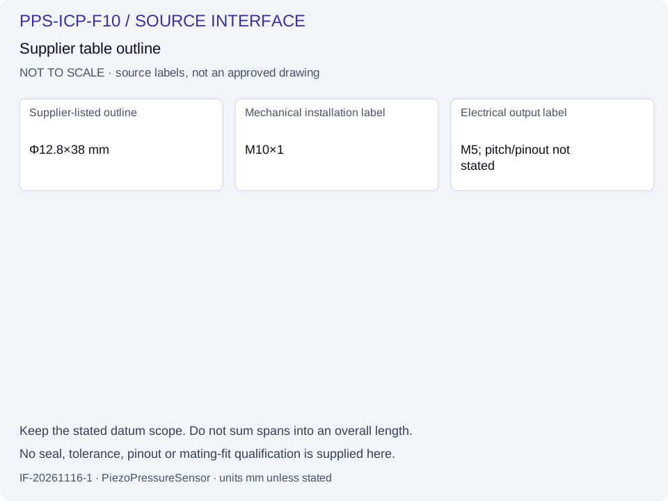
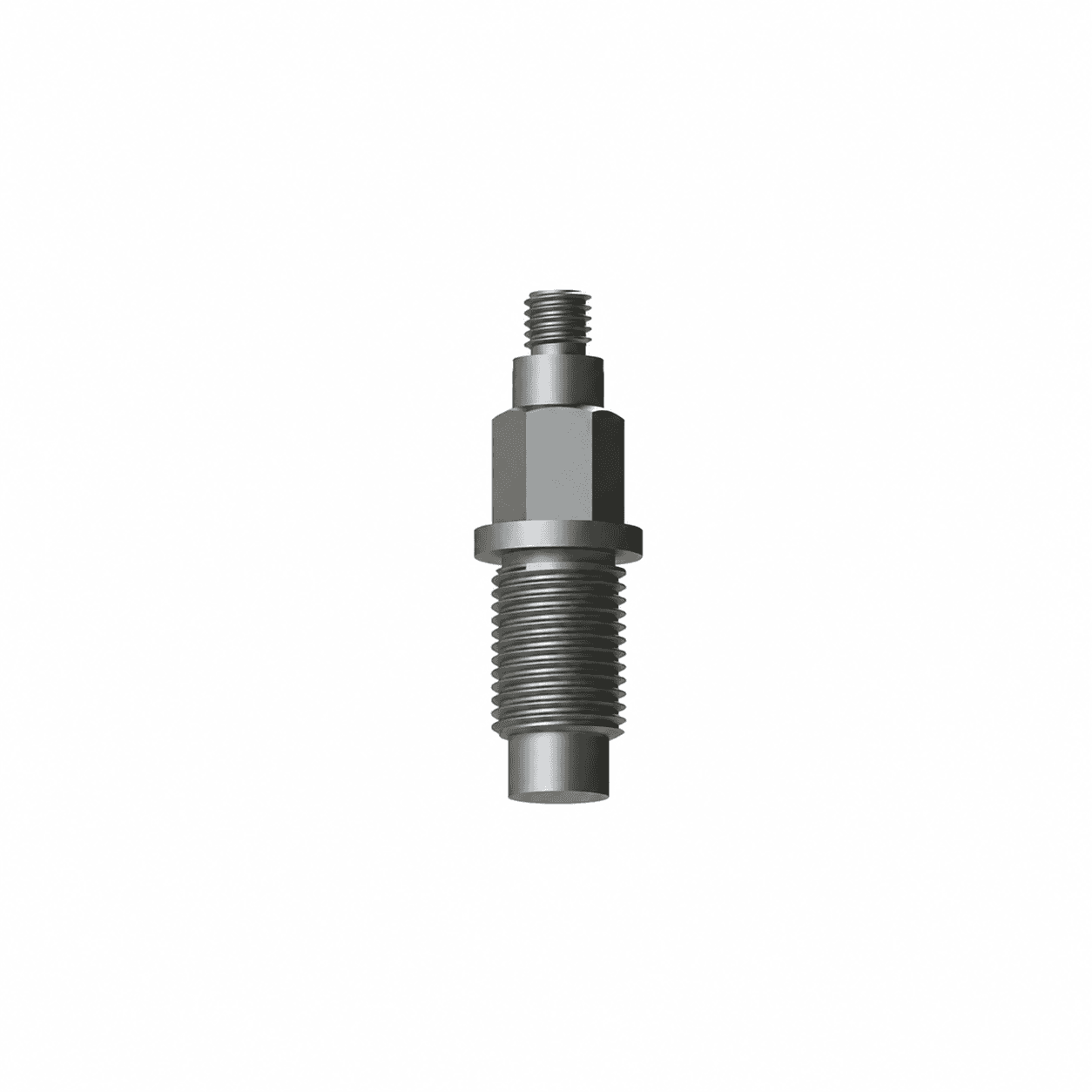
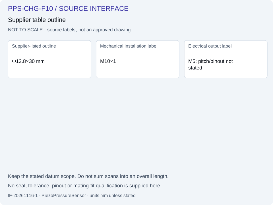
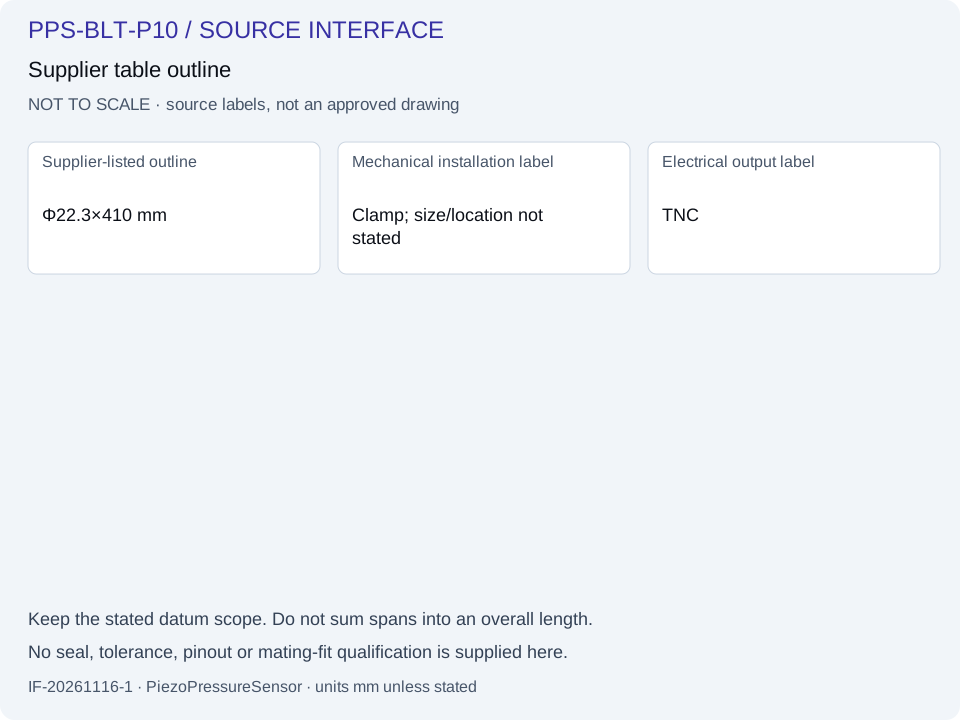
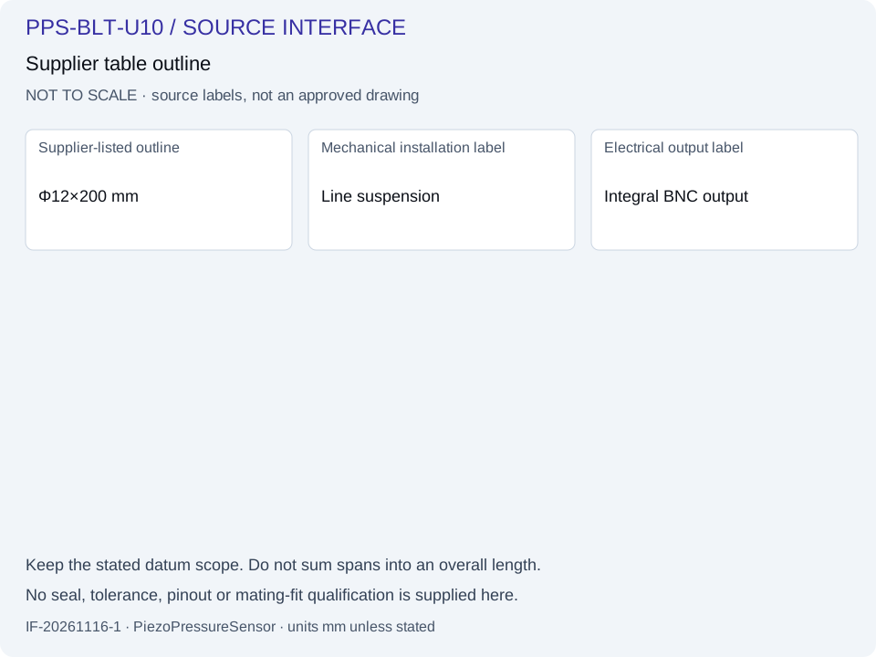
The four sourced piezoelectric configurations list diameter × outline values in a supplier table. Their images are product references without dimension arrows. The table does not define reference planes, connector inclusion, maximum installed envelope or a clamp/sensing-tip diameter. The panels therefore reproduce the stated values in text boxes without inventing a sensor silhouette or dimension endpoints.
02 / ENGINEERING NOTES
Keep each axial span tied to its source view
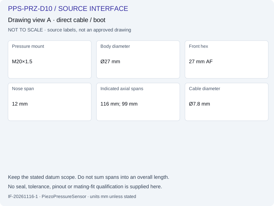
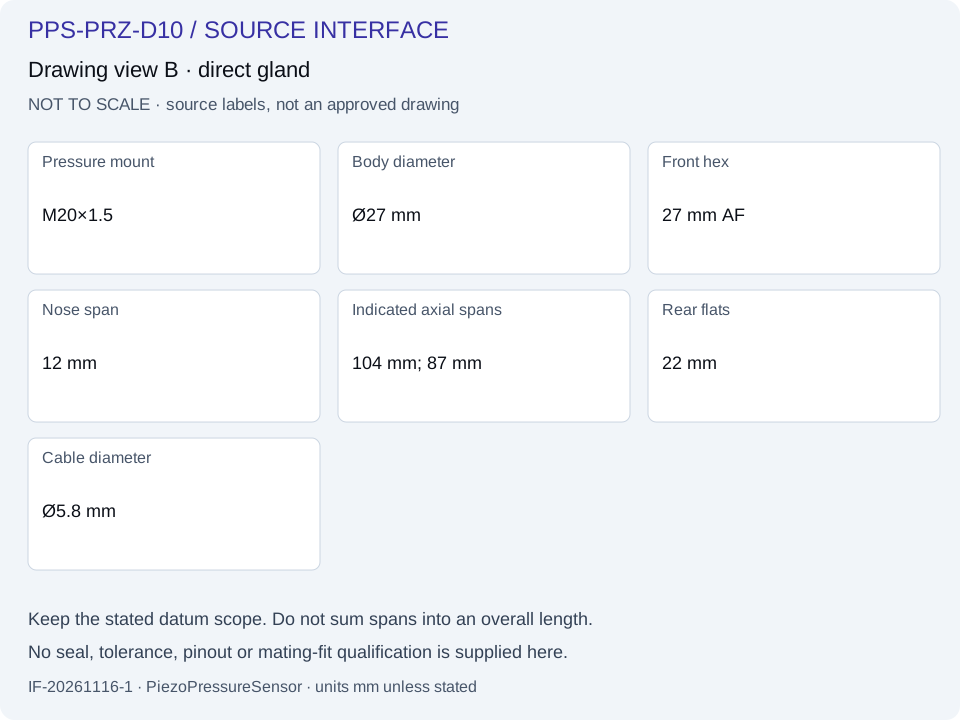
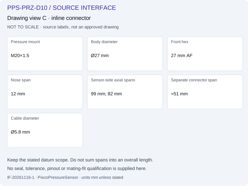
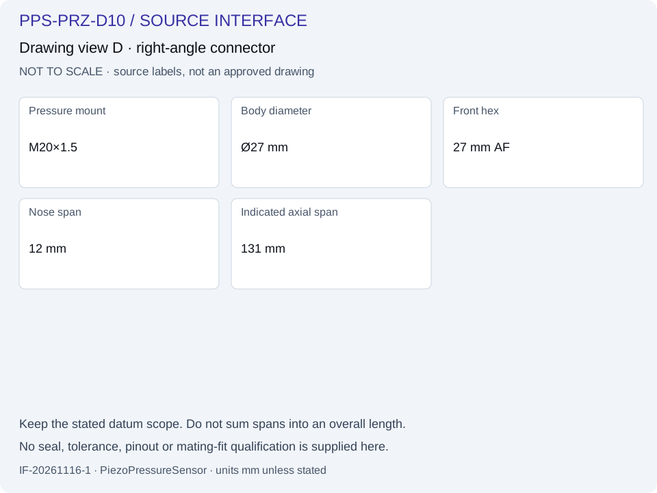
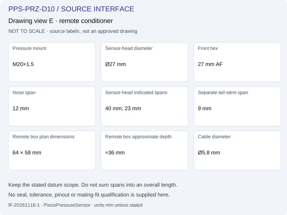
The dynamic bridge source has five separate drawing views. A view can show 104 mm and 87 mm spans while a rear gland continues beyond the indicated reference. Another shows sensor-side 99/82 mm spans and an independent approximately 51 mm connector segment. A remote-head view shows 40/23 mm head spans and a separate 9 mm tail stem. These values must not be combined into one universal overall length.
03 / ENGINEERING NOTES
A pressure-end tip diameter is not the complete assembly diameter
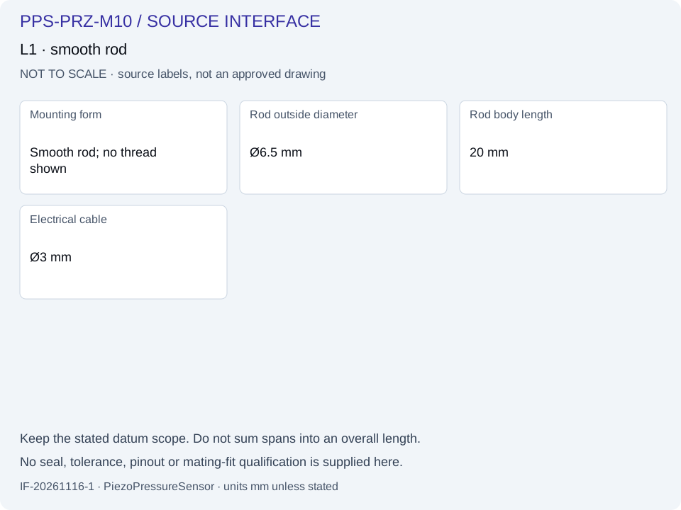
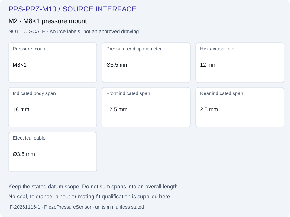
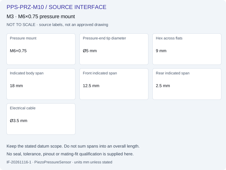
The miniature threaded sketches label a Ø5.5 mm pressure-end tip with an M8×1 mounting thread, and a Ø5 mm tip with an M6×0.75 thread. Those front features do not bound the larger thread or wrench hex. The separate smooth-rod view is Ø6.5 mm. Source range groups are retained for those views; the final ordered range, reference and interface still require confirmation.
04 / ENGINEERING NOTES
Separate the pressure mount from electrical mating
M10×1 on the flush piezoelectric sources describes mechanical installation. M5 is a separate electrical output label with no supplied pitch, gender or pinout. TNC and BNC labels also describe electrical connections rather than pressure ports. A matching connector name does not establish the cable, excitation, insulation, bias or qualified frequency response.
05 / ENGINEERING NOTES
Thread size alone cannot approve an adapter or seal
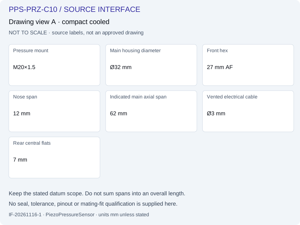
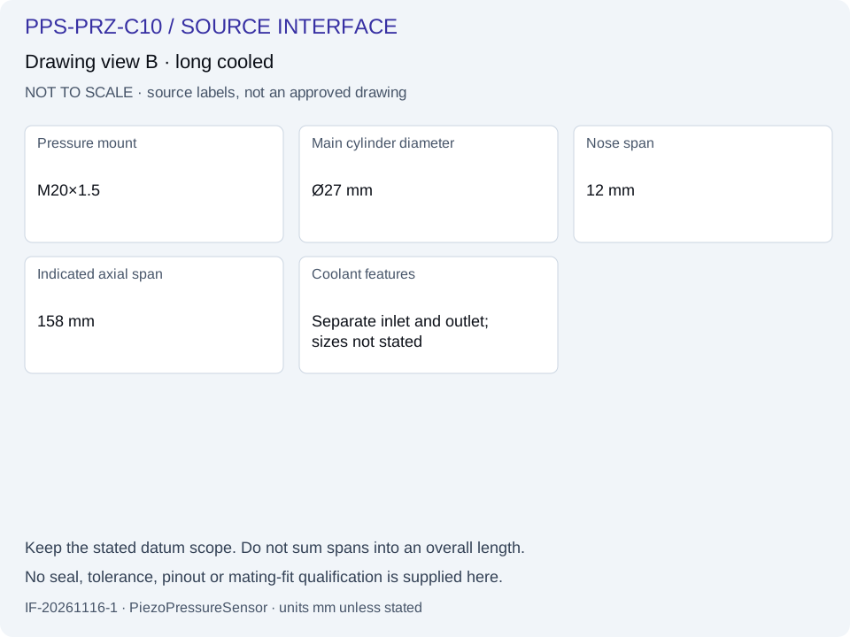
A pressure-rated installation also needs thread class and usable engagement, sealing geometry and material, diaphragm position, surface finish, torque and environmental limits. The source M20×1.5 drawings show a front nose span, but that span is not an independently qualified engagement allowance. Supply the customer port drawing and available assembly clearance before accepting a mating design.
06 / ENGINEERING NOTES
Cooled and thin arrangements need additional interface records
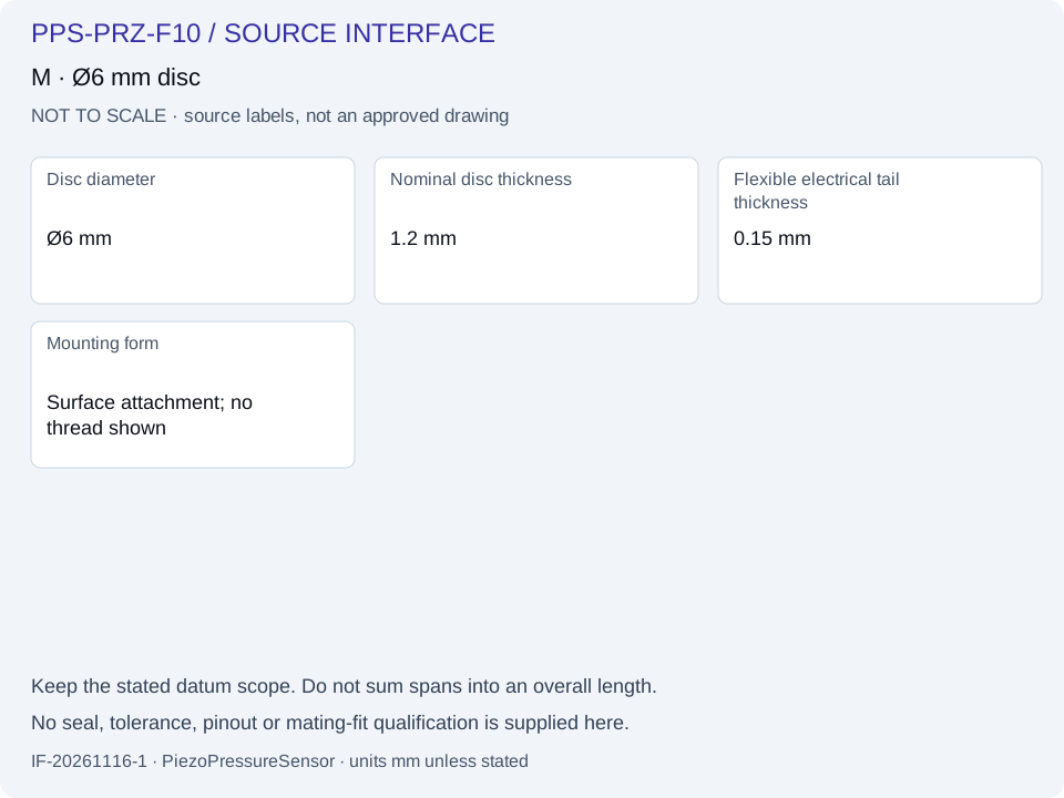
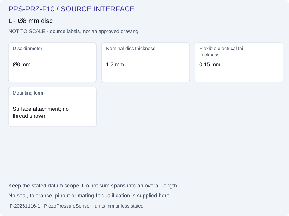
Cooling fittings, their projection, hose clearance and loss-of-cooling arrangements are separate from the pressure port and electrical output. The thin surface source supplies 1.2 mm disc thickness, Ø6/Ø8 mm options and a 0.15 mm flexible tail; it does not qualify an adhesive, recess, tail bend radius or electrical termination. A source sketch is a starting reference for the complete assembly.
07 / ENGINEERING NOTES
Request documents without assuming their availability
Choose an approved 2D installation drawing, STEP CAD if available, connector/pinout information and the required calibration/response records. These are quotation requests for the exact offered variant. The downloadable files here are source summaries; they do not create a missing STEP model, certify a pressure boundary or establish a laboratory accreditation scope.
08 / ENGINEERING NOTES
Carry the interface reference into an editable RFQ
The selected code, view and source revision identify the interface under review. Catalogue links can also carry an enumerated range into the same model. Your edited installation requirement remains available when selecting documents or accessories. A later model change clears a stale interface reference and untouched source-generated suggestions; manually edited requirements are retained for review.
Pressure-chain questions for this configuration
Are these approved installation drawings?
No. They are source-based reference summaries with stated scopes and unknowns. Request the approved exact-variant drawing before dimensional or installation acceptance.
Can I download a STEP model here?
The downloads are source interface PDFs and semantic SVG panels. STEP is an optional document request, subject to actual file availability and exact-variant confirmation.
Does a listed outline include the connector and cable?
Only where the source explicitly defines that scope. The table-only piezoelectric outlines do not define reference planes or connector inclusion.
Can I add the indicated axial spans to get total length?
Do not infer an overall length by adding spans from different views or undefined datums. Keep the source reference lines and approximate connector spans distinct.
Does the Ø5.5 mm miniature label include the thread and hex?
No. It labels the pressure-end tip on the source M8×1 sketch. The mounting thread and wrench feature are larger, separately identified features.
Is the electrical M5 label an M5×0.5 pressure port?
No. The pressure mount is separately listed as M10×1. The M5 electrical label does not supply pitch, gender, pinout or a mechanical pressure-port specification.
Does a 12 mm front span guarantee 12 mm usable engagement?
No. Usable engagement depends on thread runout, mating port, seal and the approved assembly drawing. A source span does not establish that allowance.
Does a drawing-view match prove pressure or thermal suitability?
No. Range, pressure reference, media/material compatibility, thermal duty, containment and installed response require independent acceptance for the offered assembly.
Will choosing STEP or calibration records confirm they exist?
No. The selections record what you request. Availability, applicable scope and final deliverables are confirmed during quotation.
Can I edit the installation requirement?
Yes. The RFQ installation field is editable. Manual edits survive document and accessory choices, and remain visible for review when the model changes.
Sources and scope of the comparison
- KD2004L supplier table: outline and interfaces
- KD2004 supplier table: charge-output arrangement
- KD2002L supplier table: clamp installation
- KD2101L supplier table: suspended water probe
- CYG401 source drawing and model information
- CYG409 source cooled views
- CYG507 miniature pressure-end and thread drawings
- CYG512 thin surface drawings
Original-model facts and general methods describe their named sources. They do not qualify a PPS unit or imply manufacturer affiliation.