Conditioning acceptance matrix
| Sensor output | Excitation / input | Response to request | Recorder / cable checks |
|---|---|---|---|
| IEPE voltage | Compatible constant-current drive | Amplitude/phase response at intended cable and output amplitude | Bias, compliance, output range and coax |
| Charge | Charge input range; calibrated mV/pC gain | Low-frequency droop and high-frequency response at selected gain | Insulation, low-noise charge cable and output swing |
| Bridge | Rated bridge excitation and differential input | DC baseline plus dynamic passband at selected gain | Conductor count, pinout, common-mode and gain headroom |
01 / ENGINEERING NOTES
Three input types require three different reviews
A pressure-sensor cable does not establish the conditioner input. Match the sensor output before selecting a channel count or budget.
- IEPE: constant current, compliance voltage, bias decoupling, current available for cable drive and output swing.
- Charge: input pC range, mV/pC gain, insulation, discharge time constant and suitable low-noise cable.
- Bridge: excitation voltage/current, mV/V sensitivity, zero balance, differential gain and common-mode range.
02 / ENGINEERING NOTES
Specify usable response at the selected gain
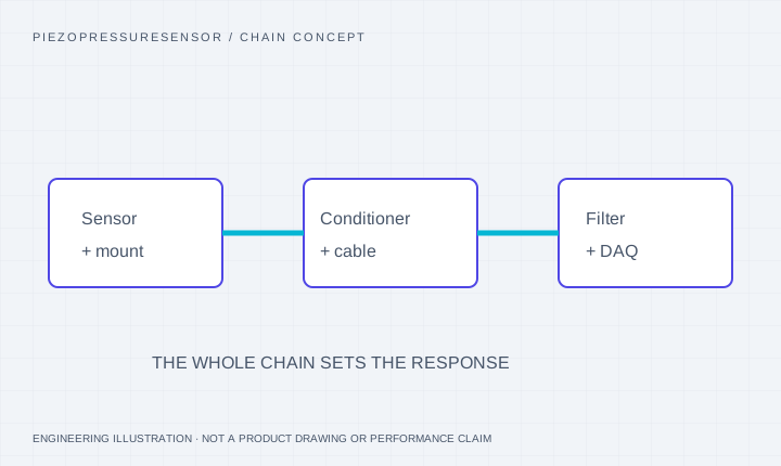
Bandwidth can fall with gain, filtering, cable loading and output amplitude. Request the amplitude/phase response of the complete setup. A single-pole 200 kHz stage has about 1.75 μs 10–90% rise time; it should not be assumed to preserve a 0.8 μs leading edge.
03 / ENGINEERING NOTES
Read two source instruments as different examples
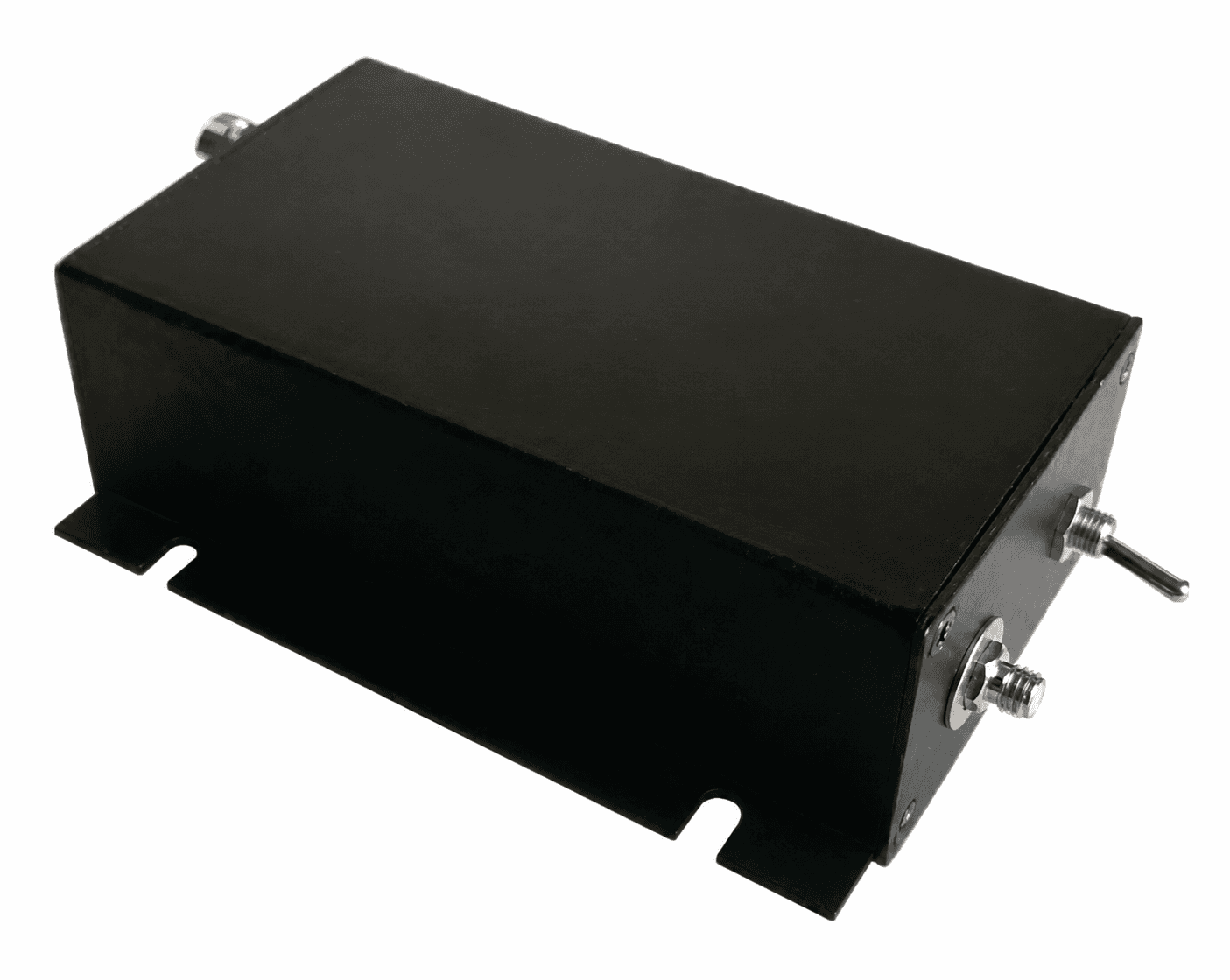
The official PCB Piezotronics 482C05 reference is a four-channel, unity-gain ICP conditioner with 2–20 mA excitation, ±10 V maximum output and a stated high-frequency response above 1,000 kHz at −5%. The sourced T499 charge-amplifier catalogue specifies 0.5 Hz–100 kHz at −3 dB±1 dB, 1–10 mV/pC and ±10 V. These are different input classes and different response definitions.
04 / ENGINEERING NOTES
Review output swing, cable and acquisition together
A nominal ±10 V conditioner can clip a recorder configured for a smaller range. Longer capacitive IEPE cables can require more drive current. Bridge and charge cables have different wiring and noise requirements.
- State the recorder model, voltage range and channel count.
- Include cable length, capacitance if known, required signal amplitude and sensor supply limits.
- Confirm power, grounding, isolation, connector gender and shield termination before a matched-bundle quote.
05 / ENGINEERING NOTES
Budget a matched instrument rather than a generic box
The USD 220–480 allowance is a starting RFQ budget, not a verified price for every multi-channel or wideband bridge system. Channel count, gain, filters, calibration and output requirements are confirmed in the written configuration.
These are source references. The T499 is a charge amplifier with a source response of 0.5 Hz–100 kHz (−3 dB±1 dB), 1–10 mV/pC gain and ±10 V output; it is not a 200 kHz IEPE instrument. Sensor temperature and conditioning limits require separate review.
SOURCE-DOCUMENTED HARDWARE REFERENCES
Review the package and its sensing principle.
These supplier-reference images show the indicated arrangements. Final pressure, medium, dimensional and response requirements are confirmed for the proposed configuration.
AT THE PRESSURE PORT
The installed passage changes the recorded event.
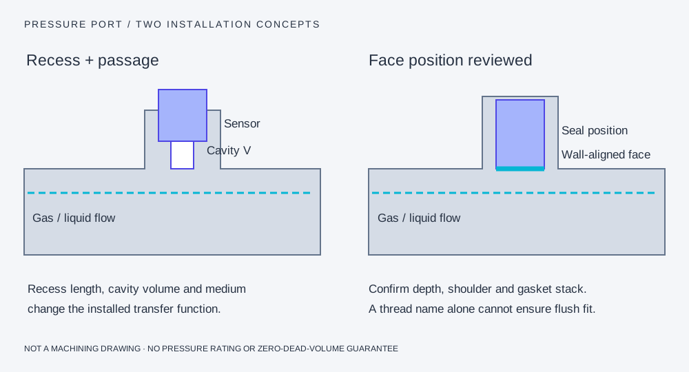
A recess adds an acoustic system.
A small cavity and connecting passage can add amplitude peaking, ringing and delay. A tapered pipe thread does not set a reproducible diaphragm depth.
Flush alignment needs dimensions.
Match the front face, sealing shoulder, gasket compression and allowed protrusion/recess. A protection layer or screen also belongs in the installed response review.
Pressure-chain questions for this configuration
Can a raw charge signal connect to an IEPE input?
A compatible charge converter or charge amplifier is needed. An IEPE current supply alone is not a charge amplifier.
Does the T499 image prove 200 kHz IEPE conditioning?
No. The sourced instrument is a charge amplifier with its own 0.5 Hz–100 kHz catalogue response. The image and data do not establish an IEPE mode or a 200 kHz rating.
Sources and scope of the comparison
Original-model facts and general methods describe their named sources. They do not qualify a PPS unit or imply manufacturer affiliation.