What each signal specification can establish
| Quantity | Useful for | Still requires review |
|---|---|---|
| One-pole −3 dB cutoff | Equivalent ideal step rise time | Flat amplitude/phase band, actual filter shape and installed response |
| Discharge time constant | Ideal single-pole plateau decay | Combined AC stages, repetition, recovery and drift |
| Per-channel sample rate | Sample interval and nominal density | Anti-alias filtering, timing, interpolation and waveform error |
| DC-capable bridge route | Static baseline plus fluctuations | Excitation, thermal offset, gain and dynamic headroom |
| Mechanical resonance | A source mechanical characteristic | Usable response; resonance is not flat measurement bandwidth |
01 / ENGINEERING NOTES
Working principle & low-frequency behavior
Piezoelectric elements generate charge when pressure changes. Leakage and the conditioning time constant gradually discharge a sustained signal. Piezoresistive elements change resistance under diaphragm strain; a powered bridge can retain DC, with offset and thermal behavior to manage.
02 / ENGINEERING NOTES
Choose the route by the measurement
Use a piezoelectric chain for dynamic pulsation when its low-frequency cutoff and pulse droop are acceptable. Review piezoresistive sensing when absolute/gauge baseline, long-duration pressure or DC plus high-frequency fluctuation is required.
- IEPE: integrated electronics and a constant-current voltage-output chain.
- Charge: external charge conditioning; insulation and cable noise are central.
- Piezoresistive: bridge excitation and a DC-coupled differential amplifier.
03 / ENGINEERING NOTES
Rise time is a whole-system requirement
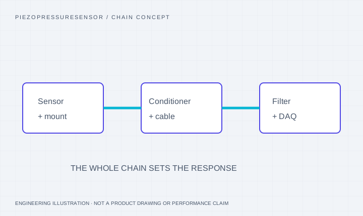
For a single-pole low-pass approximation, 10–90% rise time ≈ 0.35 / bandwidth. A 0.8 μs edge suggests about 437.5 kHz; a 200 kHz stage has about 1.75 μs rise time. These are screening estimates, not guarantees for resonant transducers. The sensor, protection, mount, cable, conditioner, filters and DAQ all contribute.
04 / ENGINEERING NOTES
Resonance, flat bandwidth & sampling are different
A 500 kHz mechanical resonance is not a 500 kHz flat measurement band. Specify an amplitude/phase tolerance and verify the installed transfer function. Sampling above Nyquist is necessary for a band-limited signal but alone does not guarantee enough points or low distortion on a fast pressure edge.
05 / ENGINEERING NOTES
Installation can dominate the error
A recess or connecting passage can add cavity resonance and delay. Thermal coatings and screens can modify response. Review them as part of the calibrated assembly. Acceleration compensation reduces a specific cross-sensitivity; it does not make installation effects disappear.
06 / ENGINEERING NOTES
Calibration evidence to request
Static calibration establishes sensitivity over defined conditions; dynamic calibration addresses response versus frequency or time. Request the reference method, range, mounting, medium, temperature, waveform, bandwidth and uncertainty. Shock-tube step testing is one possible method, not a substitute for a documented chain.
07 / ENGINEERING NOTES
Useful unit checks
1 MPa = 10 bar ≈ 145.038 psi. Therefore 50 MPa = 500 bar ≈ 7,251.9 psi. A 700 MPa request is approximately 101,526 psi. Specify absolute/gauge/differential reference alongside every range.
08 / ENGINEERING NOTES
The planner’s method and response definitions
The low-pass model is a single real pole driven by an ideal unit step: y(t)=1−exp(−t/τLP). Its 10–90% rise time is ln(9)×τLP, while its −3 dB cutoff is 1/(2π×τLP). Thus tr×f=ln(9)/(2π)=0.349699…, often rounded to 0.35. This is a derived model relation, not a measured pressure sensor response.
- Required equivalent cutoff (kHz) = 349.6991526 / desired chain rise time (μs).
- Candidate stage rise time (μs) = 349.6991526 / stage cutoff (kHz).
- A finite input edge needs a faster instrument response and an explicit error budget. Equal input and instrument rise times do not preserve the input edge accurately. Modern filters can use different constants; use their documented step response.
09 / ENGINEERING NOTES
Plateau droop is a different, low-frequency question
For one ideal high-pass pole after a positive step, retained output is exp(−T/τHP) and fractional droop d=1−exp(−T/τHP). Solving the specified loss gives τmin=−T/ln(1−d), with d expressed as a fraction. The corresponding maximum high-pass −3 dB corner is 1/(2πτmin). The low-pass and high-pass calculations are separate; the planner does not compose them into a band-pass system.
- 1% loss over 1 ms gives τmin≈99.4992 ms and fHP,max≈1.59956 Hz.
- 2% loss over 100 ms gives τmin≈4949.83 ms and fHP,max≈0.0321536 Hz.
- A −3 dB corner is not a −5% amplitude limit. Sensor, conditioner and recorder AC coupling can add multiple poles; a qualifying time constant for one stage does not qualify the entire chain.
- Repetitive pulses, baseline shift, amplifier recovery and non-flat input waveforms need their actual transfer response or measured record.
010 / ENGINEERING NOTES
Sampling density, filtering and channel count
With rise time in microseconds and rate in megasamples per second, the nominal number of sampling intervals per rise is tr×fs, and sample spacing in microseconds is 1/fs. At 5 MS/s, a 0.8 μs interval spans four sample intervals. The exact number of sample points depends on sampling phase and endpoint inclusion; interpolation does not create independent measured samples.
- Use the actual rate per enabled channel, not an aggregate maximum shared across channels.
- An ideal sharp step is not band-limited. Define the retained spectrum, analog anti-alias filter, timing and acceptable waveform error.
- A rate above twice a chosen bandwidth is not a transient-fidelity guarantee. Simultaneous sampling, trigger skew, record length and headroom also matter.
011 / ENGINEERING NOTES
Three illustrative screening exercises
Fast-edge preset: 0.8 μs chain objective, 200 kHz candidate stage, 1 ms plateau, 1% droop and 5 MS/s. The exact one-pole conversion gives about 437.124 kHz; the candidate has about 1.74850 μs rise time and is slower than the objective. The sample density is four intervals. These figures describe independent mathematical models, not an observed pressure trace.
- Long hydraulic plateau: 10 μs objective and 100 kHz stage give 34.9699 kHz equivalent and 3.49699 μs stage response. A 100 ms / 2% plateau needs a single-pole time constant of about 4.94983 s. A faster individual stage does not prove the assembled chain meets the objective.
- DC plus fluctuations: a 5 μs objective converts to about 69.9398 kHz. A 1 s / 1% AC comparison needs about 99.4992 s, but still cannot retain true DC. Review bridge excitation, drift and DC-coupled amplification.
- Increasing bandwidth or buying a long-time-constant conditioner can add cost without fixing a recessed port, clipping or incompatible excitation. First request the response and headroom for the intended complete assembly.
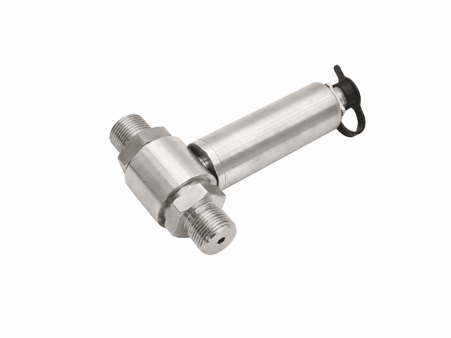
Source photographs and renderings identify the stated arrangements. Range, medium, output, installation and measured response must match the offered configuration. See each caption for its sensing principle.
SOURCE-DOCUMENTED HARDWARE REFERENCES
Review the package and its sensing principle.
These supplier-reference images show the indicated arrangements. Final pressure, medium, dimensional and response requirements are confirmed for the proposed configuration.
Pressure-chain questions for this configuration
Can a 4–20 mA transmitter detect a microsecond peak?
The output format alone does not determine speed. A process transmitter and input module with narrow bandwidth can strongly attenuate a short pulse. Evaluate the documented response of the exact chain.
Which specification should I send first?
Send peak pressure and static baseline, required rise time or flat bandwidth with tolerance, pulse duration, medium/temperature, mounting and acquisition details.
Does the calculated cutoff select a pressure sensor?
No. It is the −3 dB cutoff of an equivalent ideal one-pole chain response. It is not a flat-band specification, a resonance limit, a minimum catalogue sensor rating or a measurement accuracy margin. Review installed amplitude, phase and step response.
Why is the exact result slightly different from 0.35 divided by rise time?
The planner uses ln(9)/(2π)=0.349699… for one real low-pass pole and a 10–90% step definition. The common 0.35 rule is rounded. Other filter shapes and rise-time definitions need their own response relation.
Can a very long discharge time constant measure true DC?
A finite AC discharge time constant still loses a held signal. It can support a bounded quasi-static interval with evaluated droop, but true baseline retention needs a suitable DC-capable chain. The planner flags this distinction.
Can I apply the droop limit independently to every AC-coupled stage?
Meeting the same individual-stage limit does not establish the total loss. Sensor, conditioner and recorder high-pass stages can combine; review the full transfer function and event waveform rather than treating the single-pole output as an overall guarantee.
Do four samples across a fast edge prove it is captured accurately?
No. The result is nominal interval density, not a phase-independent point count or accuracy test. Analog bandwidth, anti-aliasing, actual per-channel rate, noise, timing and reconstruction affect the recorded edge.
What goes into the RFQ and downloaded screening brief?
The brief records the entered event requirements, optional stage and sampling inputs, DC choice, modelled results, assumptions and revision. Applying it records a separate screening brief and retains an existing manual pressure edit. The downloaded text is an engineering worksheet, not a datasheet or calibration record.
Sources and scope of the comparison
- NI: acquisition bandwidth, rise-time definitions, sampling and aliasing
- PCB: pressure sensing, discharge time constant and chain coupling
- Tektronix: bandwidth and rise-time constants depend on response shape
Original-model facts and general methods describe their named sources. They do not qualify a PPS unit or imply manufacturer affiliation.