REQUEST A CONFIGURATION / PPS SERIES
Select the signal and installation you need.
PPS codes below identify inquiry families. The table defines what to review; it does not assign an unverified pressure, temperature or bandwidth rating to a supplied unit.
| Configuration request | Pressure / task | Electrical chain | Installation review | Next step |
|---|---|---|---|---|
| PPS-BLT-PEN / PPS-BLT-LOLIncident free-field geometry | Incident overpressure + negative phase and impulse need | Sensor/output and cable drive to be selected | Pencil vs disc geometry, orientation and incident responsePCB Piezotronics 137B complete suffix | Request this family ↘ |
| PPS-BLT-UW / PPS-BLT-PVDFLiquid-coupled shockwave request | Hydrostatic baseline + transient peak, not interchangeable with wall loading | Tourmaline or PVDF chain reviewed separately | Immersion, sealing, coupling and complete high-frequency responsePCB Piezotronics 138A full variant | Request this family ↘ |
| PPS-BLT-TOAShock-front timing request | Arrival-time threshold and local pressure environment | Timing filter and acquisition interface need separate review | ToA timing purpose is distinct from calibrated full pressure waveformFull original ToA model required | Request this family ↘ |
DOCUMENTED CONFIGURATION OPTIONS
Start with a specific range and signal interface.
These PPS codes map to the named source arrangements. Source values guide quotation review; acceptance applies to the exact offered assembly.
DYNAMIC / AC SIGNAL
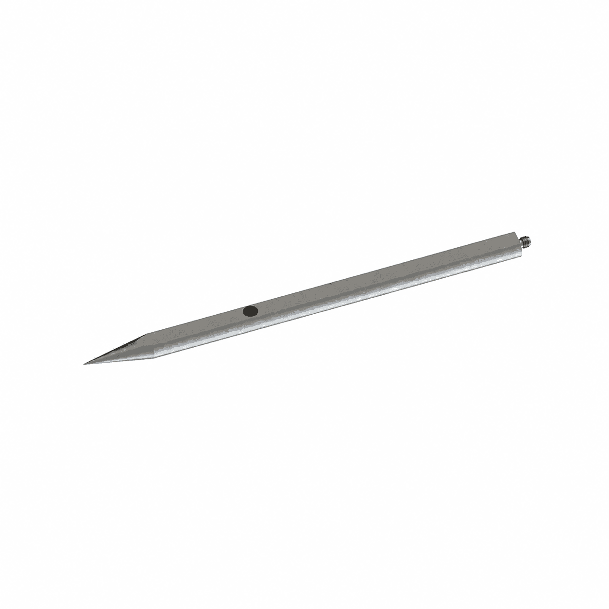
PPS-BLT-P10
Free-field IEPE air-probe configuration
Dynamic pressure excursion; static preload/reference to confirm
Source-documented configuration · quotation review required
- Output
- IEPE voltage output
- Pressure reference
- Dynamic pressure excursion; static preload/reference to confirm
- Source temperature
- -40 to +120 deg C; exact duty to confirm
- Mount
- clamp
- Electrical connection
- TNC
- Body envelope
- 22.3 x 410 mm; source dimensions, not a port drawing
- Excitation
- 24-28 VDC supply; source table 2-10 mA; cable-drive review required
Source catalogue full-scale options. Reference, static loading, negative phase and exact ordered variant require review.
Review PPS-BLT-P10 dimensions & interfaces ↗Source values & acceptance checks · PPS-BLT-P10
| Full scale | Source sensitivity | Natural / resonant frequency | Catalogue rise time | Variant note |
|---|---|---|---|---|
| 1 MPa / 10 bar / 145.0 psi | 5000 mV/MPa | ≥250 kHz | ≤2 us | high-piezoelectric crystal; composition unspecified |
| 5 MPa / 50 bar / 725.2 psi | 1000 mV/MPa | ≥250 kHz | ≤2 us | high-piezoelectric crystal; composition unspecified |
| 25 MPa / 250 bar / 3625.9 psi | 200 mV/MPa | ≥250 kHz | ≤2 us | quartz |
| 50 MPa / 500 bar / 7251.9 psi | 100 mV/MPa | ≥250 kHz | ≤2 us | quartz |
| 100 MPa / 1000 bar / 14503.8 psi | 50 mV/MPa | ≥250 kHz | ≤2 us | quartz |
Catalogue resonance and rise-time labels are not calibrated flat bandwidth. Rise-time percentage and incident/reflected geometry are not established by this table.
Confirm before a final specification
- Confirm medium/wetted-material compatibility and pressure reference.
- Obtain the approved installation drawing, seal, torque and connector pinout.
- Request the installed amplitude/phase response and calibration scope.
- Source table lists 2-10 mA while long-cable prose suggests over 10 mA; reconcile against the selected electronics before use.
- Free-field air arrangement; source rise-time geometry is not defined. Not a validated ToA microsensor.
This is catalogue evidence, not a serial-unit calibration certificate, stock confirmation or approved manufacturing drawing.
DYNAMIC / AC SIGNAL
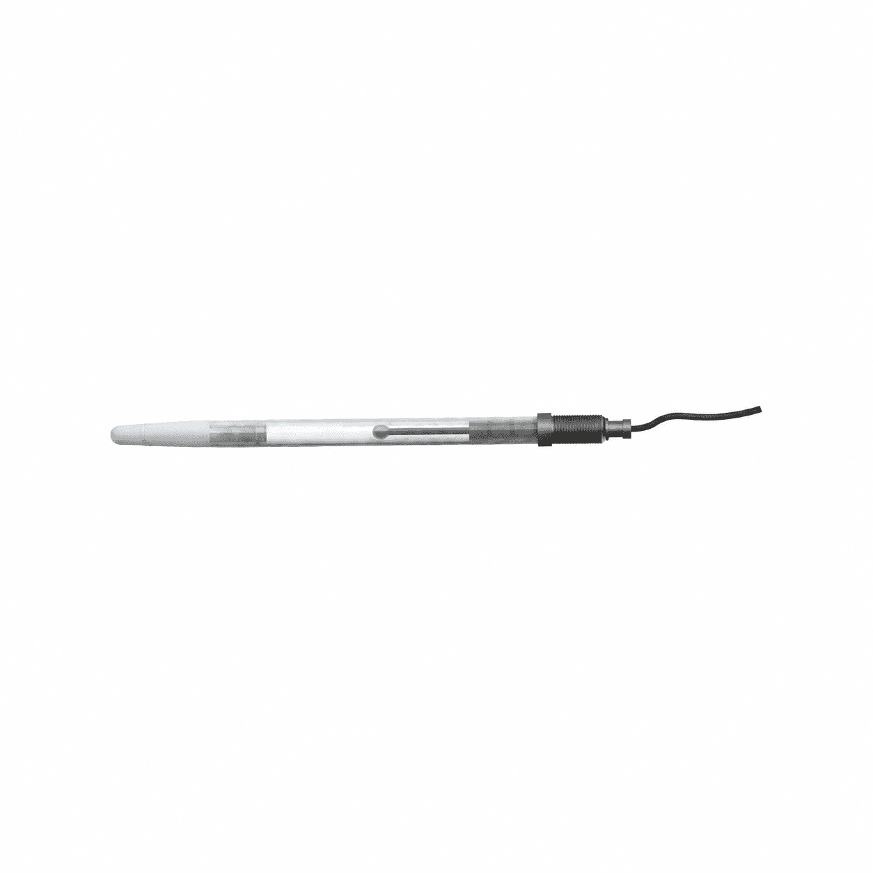
PPS-BLT-U10
Tourmaline IEPE water-probe configuration
Dynamic pressure excursion; static preload/reference to confirm
Source-documented configuration · quotation review required
- Output
- Tourmaline with IEPE electronics
- Pressure reference
- Dynamic pressure excursion; static preload/reference to confirm
- Source temperature
- -20 to +50 deg C; exact duty to confirm
- Mount
- suspended/free-field
- Electrical connection
- integral BNC
- Body envelope
- 12 x 200 mm; source dimensions, not a port drawing
- Excitation
- 24-28 VDC supply; source table 2-10 mA; cable-drive review required
Source catalogue full-scale options. Reference, static loading, negative phase and exact ordered variant require review.
Review PPS-BLT-U10 dimensions & interfaces ↗Source values & acceptance checks · PPS-BLT-U10
| Full scale | Source sensitivity | Natural / resonant frequency | Catalogue rise time | Variant note |
|---|---|---|---|---|
| 7 MPa / 70 bar / 1015.3 psi | 700 mV/MPa | ≥1000 kHz | ≤1.5 us | tourmaline |
| 20 MPa / 200 bar / 2900.8 psi | 250 mV/MPa | ≥1000 kHz | ≤1.5 us | tourmaline |
| 50 MPa / 500 bar / 7251.9 psi | 100 mV/MPa | ≥1000 kHz | ≤1.5 us | tourmaline |
| 100 MPa / 1000 bar / 14503.8 psi | 50 mV/MPa | ≥1000 kHz | ≤1.5 us | tourmaline |
Catalogue resonance and rise-time labels are not calibrated flat bandwidth. Rise-time percentage and incident/reflected geometry are not established by this table.
Confirm before a final specification
- Confirm medium/wetted-material compatibility and pressure reference.
- Obtain the approved installation drawing, seal, torque and connector pinout.
- Request the installed amplitude/phase response and calibration scope.
- Source table lists 2-10 mA while long-cable prose suggests over 10 mA; reconcile against the selected electronics before use.
- Tourmaline IEPE, not PVDF; source <=1.5 us is not a 50 ns hydrophone specification.
This is catalogue evidence, not a serial-unit calibration certificate, stock confirmation or approved manufacturing drawing.
01 / ENGINEERING NOTES
Air blast & shock-tube measurement
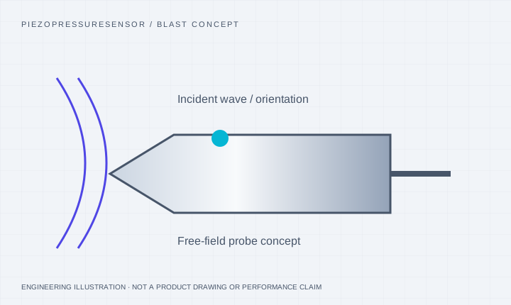
A pencil probe presents a streamlined geometry to an incident pressure wave. A flush wall transducer measures a different boundary condition. Reflected pressure cannot be substituted for incident pressure without a justified analysis.
- Specify peak overpressure, expected baseline, pulse duration and rise-time objective.
- Provide orientation, stand-off, mounting arrangement, triggering and acquisition requirements.
- PCB 137B references are identifiers for comparison only; complete suffixes and calibration conditions are needed.
02 / ENGINEERING NOTES
Underwater shockwave & cavitation
Tourmaline or PVDF sensing approaches may be considered for liquid-coupled pressure transients. Selection depends on immersion depth, hydrostatic baseline, chemical compatibility, pulse spectrum, sealing and cable behavior.
- Separate hydrostatic load from transient peak and any negative pressure phase.
- Confirm mechanical and acoustic installation, cable length and connector sealing. A free-field water probe is not automatically suitable for wall-impingement cavitation measurements.
- PCB 138A references are review starting points, not evidence of underwater interchangeability.
03 / ENGINEERING NOTES
Protect the diaphragm without hiding the pulse
Ablative coatings and screens can reduce some thermal effects but also alter transmission. Request protection qualified with the exact sensing and mounting assembly. Fire-flash immunity and unchanged rise time must not be assumed.
04 / ENGINEERING NOTES
Evidence to request with a proposed configuration
Ask for dynamic response under defined test conditions, calibrated sensitivity and uncertainty, measurement versus survival limits, and repeatability across the required pulse sequence. A static calibration alone does not establish shockwave fidelity.
ORIGINAL-MODEL DATA / INDEPENDENT REVIEW
Keep original specifications separate from a proposed replacement.
Facts below describe the named original models. A PPS configuration still needs its own dimensional, electrical and calibration evidence. Resonance and flat bandwidth are different quantities.
| Original model & source | Verified reference facts | Compatibility check | Review request |
|---|---|---|---|
| PCB Piezotronics 137B23B | 50 psi / 3.447 bar; 100 mV/psi; incident rise time ≤6.5 μs; BNC. | Incident rise time is 6.5 µs, not the ≤1 µs reflected response of 113B/102B. No general sub-microsecond claim is justified across blast families. | Review this original ↘ |
| PCB Piezotronics 138A05 | 5,000 psi / 344.7 bar; tourmaline ICP; reflected rise time ≤1.5 μs. | Water coupling, hydrostatic loading and exact suffix matter; this is not evidence for a PPS underwater rating. | Review this original ↘ |
No affiliation or universal interchangeability is implied. Pressure-port threads and electrical connector threads must be checked separately.
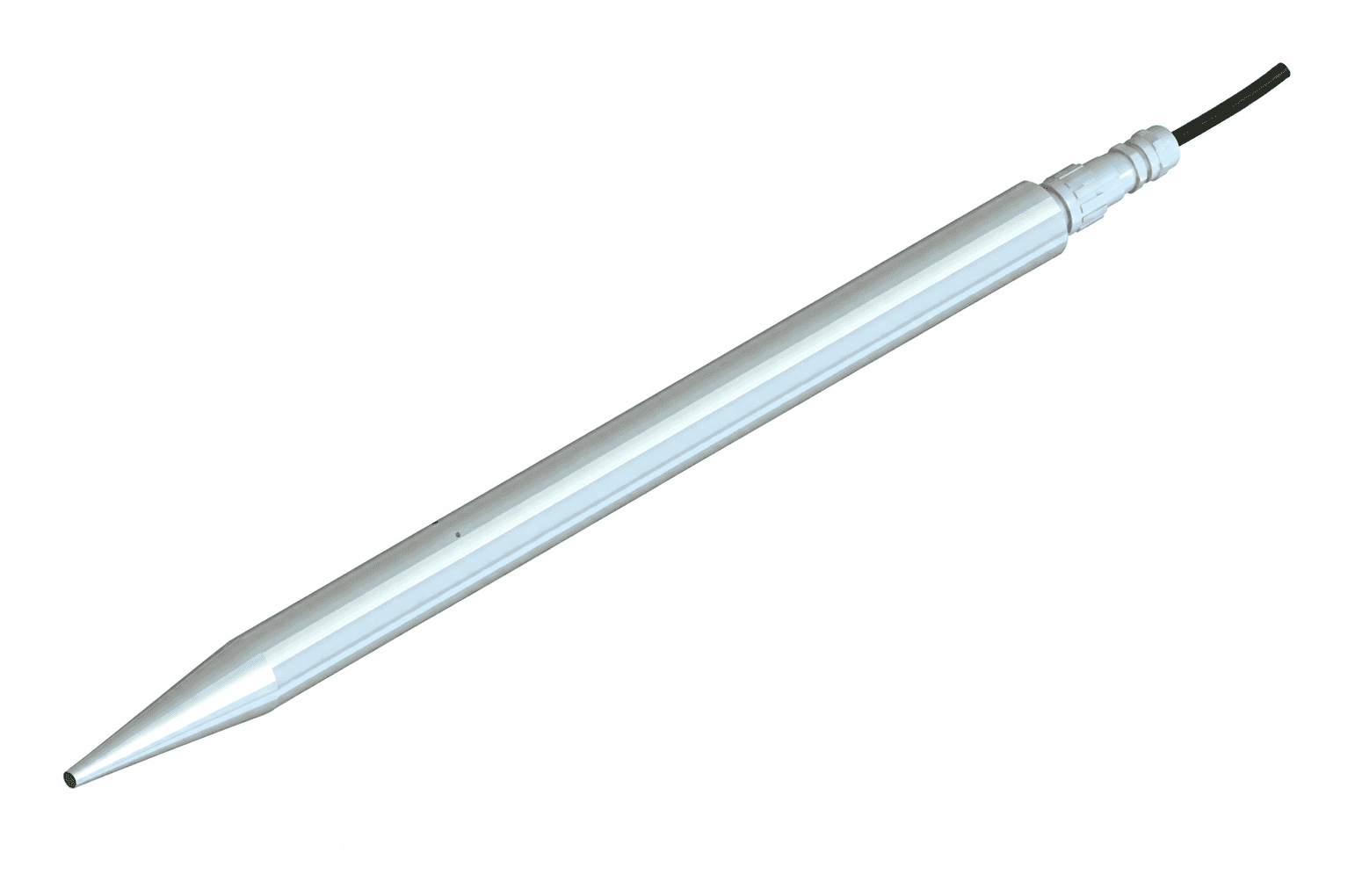
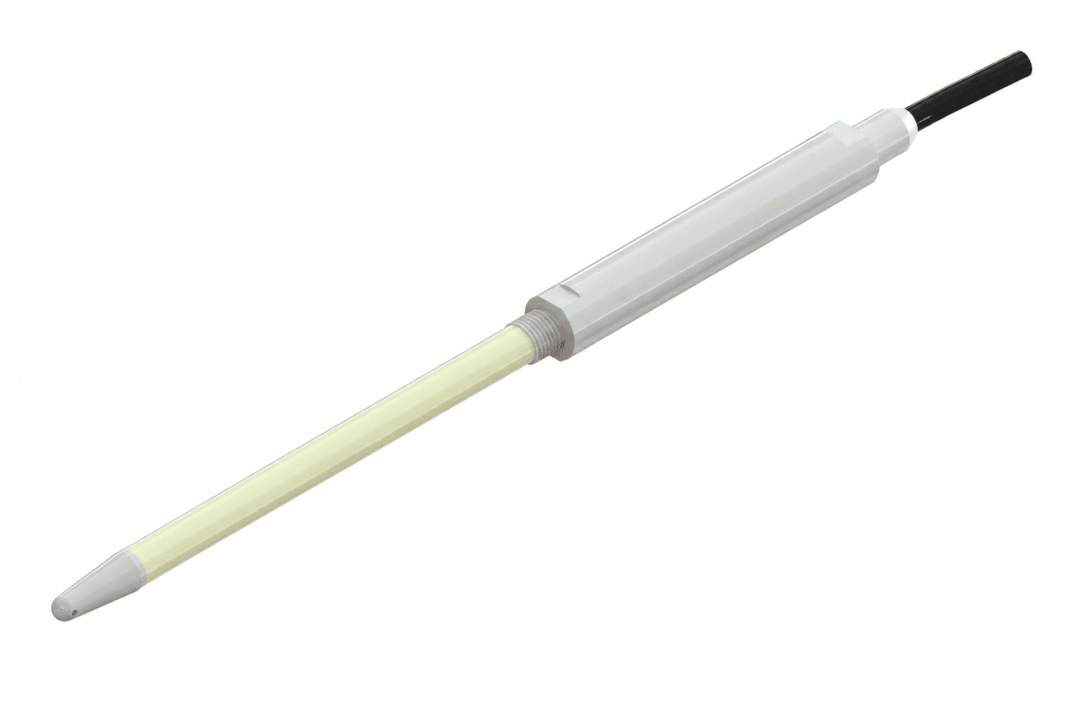
The KD2002L rendering is an IEPE piezoelectric air probe; KD2101L is an IEPE tourmaline water probe. CYG1414 and CYG1413 show separate piezoresistive alternatives. None depicts a PVDF needle hydrophone; qualify each signal chain and measurement geometry separately.
SOURCE-DOCUMENTED HARDWARE REFERENCES
Review the package and its sensing principle.
These supplier-reference images show the indicated arrangements. Final pressure, medium, dimensional and response requirements are confirmed for the proposed configuration.
AT THE PRESSURE PORT
The installed passage changes the recorded event.
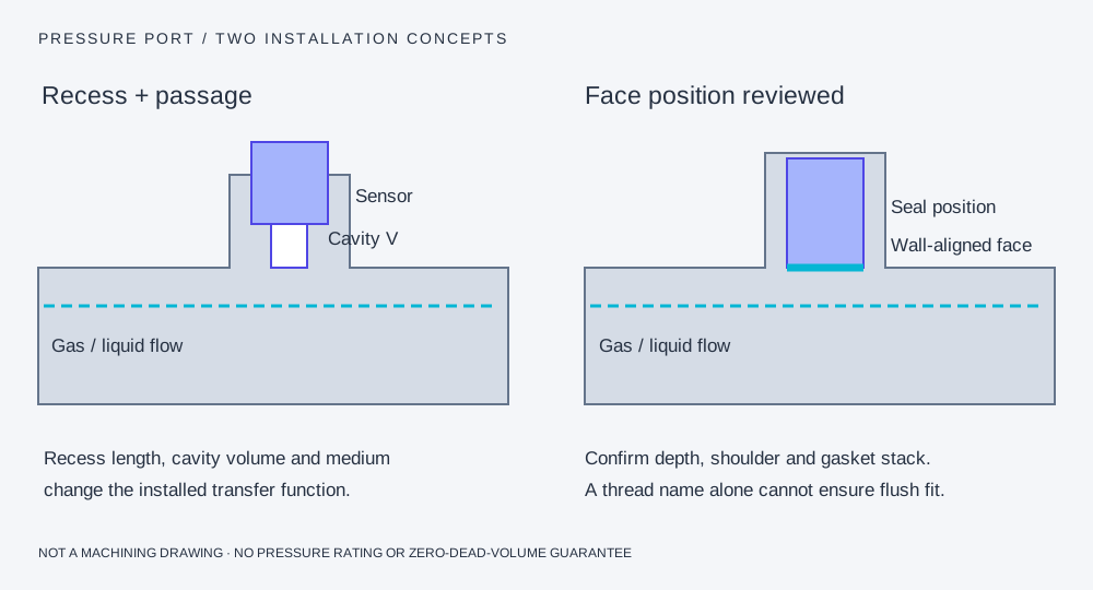
A recess adds an acoustic system.
A small cavity and connecting passage can add amplitude peaking, ringing and delay. A tapered pipe thread does not set a reproducible diaphragm depth.
Flush alignment needs dimensions.
Match the front face, sealing shoulder, gasket compression and allowed protrusion/recess. A protection layer or screen also belongs in the installed response review.
Pressure-chain questions for this configuration
Can one probe cover air and underwater tests?
Only when the complete configuration is qualified for both environments. Liquid coupling, baseline pressure, sealing and frequency response need separate review.
Are probe price and delivery fixed?
No. Quantity, range, conditioning, calibration and destination determine the written quotation and delivery schedule.
Sources and scope of the comparison
Original-model facts and general methods describe their named sources. They do not qualify a PPS unit or imply manufacturer affiliation.