01 / ENGINEERING NOTES
First draw the actual diaphragm and seal stack
Record the local wall, front face, shoulder, gasket compression, thread engagement and permitted recess/protrusion. Straight-thread shoulder sealing can control an axial stop; a tapered pipe-thread engagement alone cannot establish the same position on every port.
02 / ENGINEERING NOTES
Two acoustic approximations answer different questions
A lumped cavity with a neck can be screened using f_H = c/(2π) × √[S/(V × l_eff)]. Here c is sound speed in the actual medium, S the neck area, V the cavity volume and l_eff the effective neck length. The model assumes appropriate small acoustic dimensions and a defined cavity/neck. It is not a pressure-rating calculation.
03 / ENGINEERING NOTES
A connecting passage is not automatically a Helmholtz cavity
For a simplified gas passage, a quarter-wave estimate f ≈ c/(4L) may be useful under the assumed boundary conditions. For example, c = 343 m/s and L = 0.003 m give about 28.6 kHz. This synthetic example is an acoustic screening estimate, not a measured port response or a universal bandwidth limit.
04 / ENGINEERING NOTES
Protection changes amplitude, phase and heat transfer
An ablative layer, screen, recess or cooling mount may reduce specific exposures while changing the pressure transmission. Do not apply one coating thickness or material to every diaphragm. Review thermal flash, sustained temperature, particle impact and chemical compatibility separately.
05 / ENGINEERING NOTES
Validate the mounted assembly you will use
Request the installed response and pressure/temperature compatibility for the selected sensor, adapter, seal and protection. Keep the acceptance limits in the RFQ and drawing review.
- Face location and sealing geometry: measured or drawing-controlled.
- Pressure and thermal ratings: specific materials and complete assembly.
- Dynamic acceptance: amplitude/phase, pulse shape, droop and uncertainty.
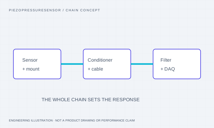
- Conditioner/cable/DAQ: excitation, gain, filtering and headroom.
AT THE PRESSURE PORT
The installed passage changes the recorded event.
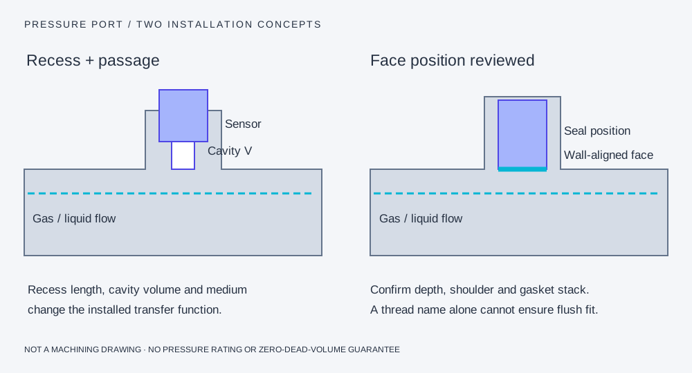
A recess adds an acoustic system.
A small cavity and connecting passage can add amplitude peaking, ringing and delay. A tapered pipe thread does not set a reproducible diaphragm depth.
Flush alignment needs dimensions.
Match the front face, sealing shoulder, gasket compression and allowed protrusion/recess. A protection layer or screen also belongs in the installed response review.
Pressure-chain questions for this configuration
Can an NPT adapter guarantee zero dead volume?
A generic thread designation cannot guarantee the diaphragm position. Confirm the actual wall, seal and adapter dimensions and validate the installed response.
Can I use the example cavity formula as a machining specification?
No. It is an acoustic screening model under stated assumptions. The pressure-rated mechanical design and actual installed response require separate engineering evidence.
Sources and scope of the comparison
- PCB pressure installation and thermal guidance
- PCB manual: passage resonance and model-specific protection
- NIST pressure-tubing transfer-function study
Original-model facts and general methods describe their named sources. They do not qualify a PPS unit or imply manufacturer affiliation.