PiezoPressureSensor.
Menu

PPS CONFIGURATIONS / RANGE TO RFQ

Select a Dynamic Pressure Sensor Configuration

Filter source-documented arrangements, compare their interfaces and carry a selected model and range into your inquiry.

Browse configurations ↓

Technical content reviewed 16 November 2026 · PiezoPressureSensor

Narrow eight documented pressure configurations.

Optional catalogue filters

Pressure screening compares documented full-scale options only. It does not establish operating headroom, pressure-reference compatibility or usable bandwidth. The cooled model's unpaired envelope is excluded when a numeric minimum is entered. Text searches include catalogue limits; a keyword match does not establish a capability.

Preparing filters; all documented configurations are listed below.How the screening works ↓
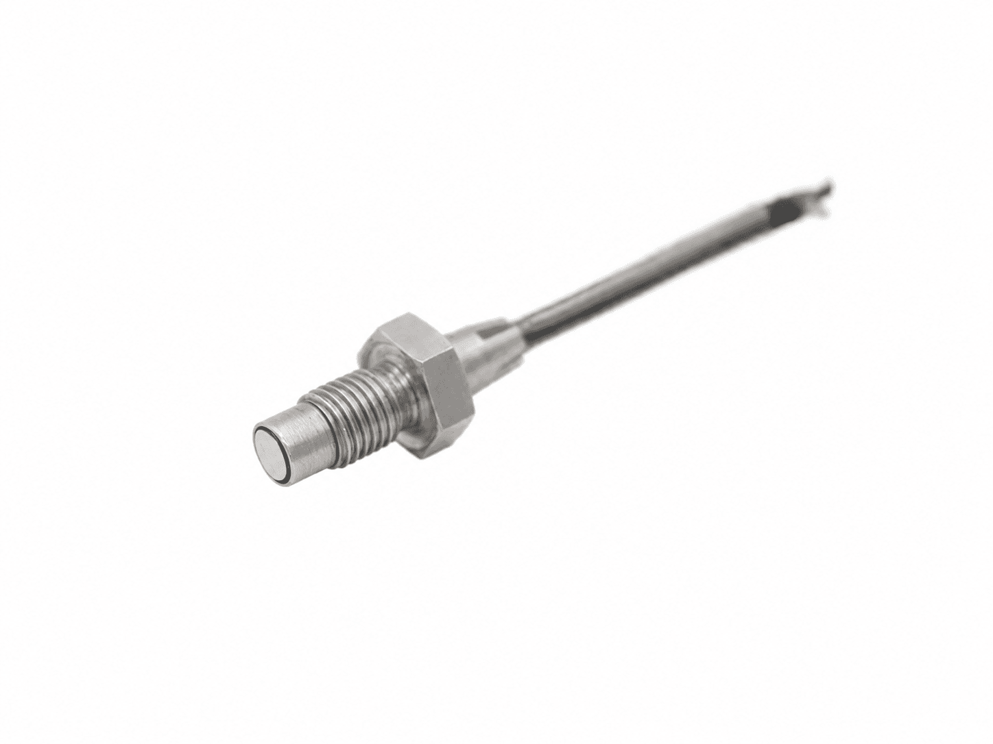
IEPE piezoelectric pressure-sensor configuration reference — supplier rendering.
Edited supplier rendering · KD2004L

DYNAMIC / AC SIGNAL

PPS-ICP-F10

Flush IEPE pressure configuration

Dynamic pressure excursion; static preload/reference to confirm

Source-documented configuration · quotation review required

Output
IEPE voltage output
Pressure reference
Dynamic pressure excursion; static preload/reference to confirm
Source temperature
-40 to +120 deg C; exact duty to confirm
Mount
M10×1
Electrical connection
M5
Body envelope
12.8 x 38 mm; source dimensions, not a port drawing
Excitation
24-28 VDC supply; source table 2-10 mA; cable-drive review required

Source catalogue full-scale options. Reference, static loading, negative phase and exact ordered variant require review.

Review PPS-ICP-F10 dimensions & interfaces ↗
Source values & acceptance checks · PPS-ICP-F10
KD2004L source pairs · checked 2026-11-16
Full scaleSource sensitivityNatural / resonant frequencyCatalogue rise timeVariant note
1 MPa / 10 bar / 145.0 psi5000 mV/MPa≥200 kHz≤2 ushigh-piezoelectric crystal; composition unspecified
5 MPa / 50 bar / 725.2 psi1000 mV/MPa≥200 kHz≤2 ushigh-piezoelectric crystal; composition unspecified
20 MPa / 200 bar / 2900.8 psi250 mV/MPa≥200 kHz≤2 usquartz
50 MPa / 500 bar / 7251.9 psi100 mV/MPa≥200 kHz≤2 usquartz
100 MPa / 1000 bar / 14503.8 psi50 mV/MPa≥200 kHz≤2 usquartz

Catalogue resonance and rise-time labels are not calibrated flat bandwidth. Rise-time percentage and incident/reflected geometry are not established by this table.

Confirm before a final specification

  • Confirm medium/wetted-material compatibility and pressure reference.
  • Obtain the approved installation drawing, seal, torque and connector pinout.
  • Request the installed amplitude/phase response and calibration scope.
  • M10x1 is the pressure mount. The electrical connector is labeled M5 without pitch/pinout; do not infer M5x0.5 or 10-32.
  • Source table lists 2-10 mA while long-cable prose suggests over 10 mA; reconcile against the selected electronics before use.
KD2004L supplier catalogue ↗

This is catalogue evidence, not a serial-unit calibration certificate, stock confirmation or approved manufacturing drawing.

Charge-output piezoelectric pressure-sensor reference — supplier rendering.
Edited supplier rendering · KD2004

DYNAMIC / AC SIGNAL

PPS-CHG-F10

Flush charge-output pressure configuration

Dynamic pressure excursion; static preload/reference to confirm

Source-documented configuration · quotation review required

Output
Charge, external amplifier required
Pressure reference
Dynamic pressure excursion; static preload/reference to confirm
Source temperature
-40 to +150 deg C; exact duty to confirm
Mount
M10×1
Electrical connection
M5
Body envelope
12.8 x 30 mm; source dimensions, not a port drawing
Conditioning
Charge amplifier; match sensitivity, insulation, input charge and time constant

Source catalogue full-scale options. Reference, static loading, negative phase and exact ordered variant require review.

Review PPS-CHG-F10 dimensions & interfaces ↗
Source values & acceptance checks · PPS-CHG-F10
KD2004 source pairs · checked 2026-11-16
Full scaleSource sensitivityNatural / resonant frequencyCatalogue rise timeVariant note
1 MPa / 10 bar / 145.0 psi5000 pC/MPa≥200 kHz≤2 ushigh-piezoelectric crystal; composition unspecified
5 MPa / 50 bar / 725.2 psi2000 pC/MPa≥200 kHz≤2 ushigh-piezoelectric crystal; composition unspecified
20 MPa / 200 bar / 2900.8 psi1000 pC/MPa≥200 kHz≤2 ushigh-piezoelectric crystal; composition unspecified
60 MPa / 600 bar / 8702.3 psi120 pC/MPa≥200 kHz≤2 usquartz

Catalogue resonance and rise-time labels are not calibrated flat bandwidth. Rise-time percentage and incident/reflected geometry are not established by this table.

Confirm before a final specification

  • Confirm medium/wetted-material compatibility and pressure reference.
  • Obtain the approved installation drawing, seal, torque and connector pinout.
  • Request the installed amplitude/phase response and calibration scope.
  • M10x1 is the pressure mount. The electrical connector is labeled M5 without pitch/pinout; do not infer M5x0.5 or 10-32.
  • The source is limited to +150 deg C. It does not establish a +650 deg C or hydrogen-qualified assembly. A copied current-drive paragraph is not a charge-sensor supply specification.
KD2004 supplier catalogue ↗

This is catalogue evidence, not a serial-unit calibration certificate, stock confirmation or approved manufacturing drawing.

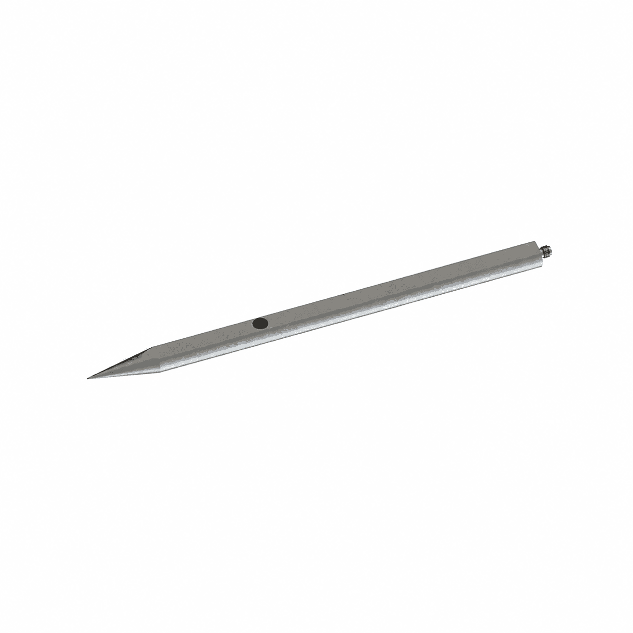
IEPE piezoelectric air-blast pencil-probe reference — supplier rendering.
Edited supplier rendering · KD2002L

DYNAMIC / AC SIGNAL

PPS-BLT-P10

Free-field IEPE air-probe configuration

Dynamic pressure excursion; static preload/reference to confirm

Source-documented configuration · quotation review required

Output
IEPE voltage output
Pressure reference
Dynamic pressure excursion; static preload/reference to confirm
Source temperature
-40 to +120 deg C; exact duty to confirm
Mount
clamp
Electrical connection
TNC
Body envelope
22.3 x 410 mm; source dimensions, not a port drawing
Excitation
24-28 VDC supply; source table 2-10 mA; cable-drive review required

Source catalogue full-scale options. Reference, static loading, negative phase and exact ordered variant require review.

Review PPS-BLT-P10 dimensions & interfaces ↗
Source values & acceptance checks · PPS-BLT-P10
KD2002L source pairs · checked 2026-11-16
Full scaleSource sensitivityNatural / resonant frequencyCatalogue rise timeVariant note
1 MPa / 10 bar / 145.0 psi5000 mV/MPa≥250 kHz≤2 ushigh-piezoelectric crystal; composition unspecified
5 MPa / 50 bar / 725.2 psi1000 mV/MPa≥250 kHz≤2 ushigh-piezoelectric crystal; composition unspecified
25 MPa / 250 bar / 3625.9 psi200 mV/MPa≥250 kHz≤2 usquartz
50 MPa / 500 bar / 7251.9 psi100 mV/MPa≥250 kHz≤2 usquartz
100 MPa / 1000 bar / 14503.8 psi50 mV/MPa≥250 kHz≤2 usquartz

Catalogue resonance and rise-time labels are not calibrated flat bandwidth. Rise-time percentage and incident/reflected geometry are not established by this table.

Confirm before a final specification

  • Confirm medium/wetted-material compatibility and pressure reference.
  • Obtain the approved installation drawing, seal, torque and connector pinout.
  • Request the installed amplitude/phase response and calibration scope.
  • Source table lists 2-10 mA while long-cable prose suggests over 10 mA; reconcile against the selected electronics before use.
  • Free-field air arrangement; source rise-time geometry is not defined. Not a validated ToA microsensor.
KD2002L supplier catalogue ↗

This is catalogue evidence, not a serial-unit calibration certificate, stock confirmation or approved manufacturing drawing.

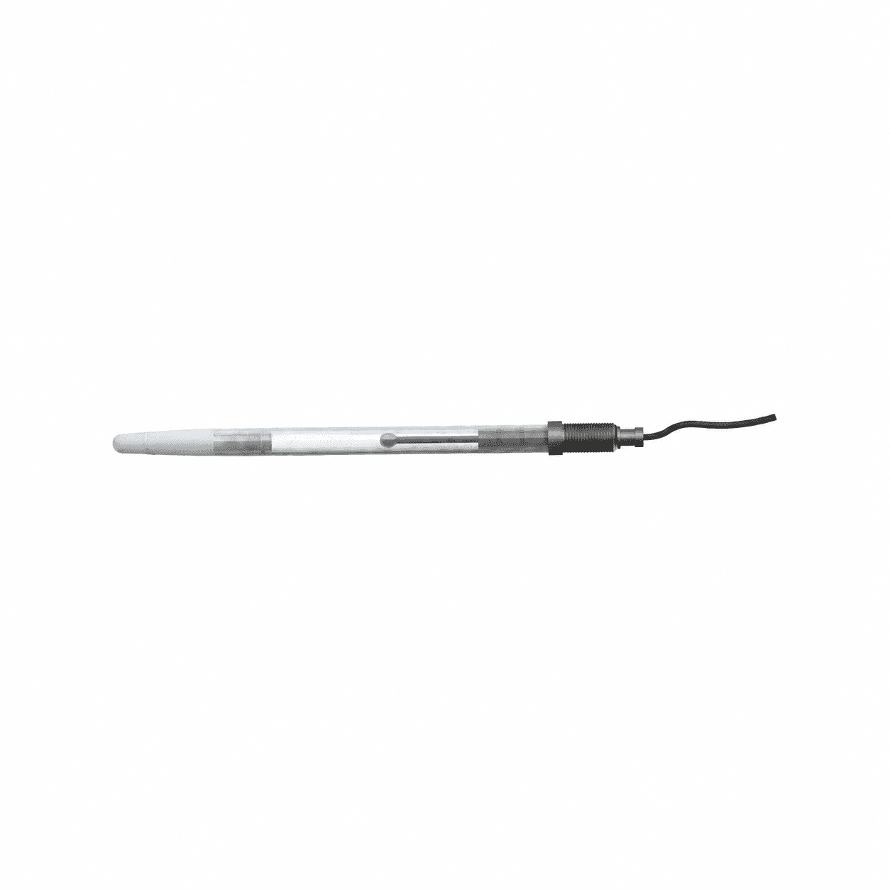
Tourmaline IEPE underwater free-field probe reference — supplier rendering.
Edited supplier rendering · KD2101L

DYNAMIC / AC SIGNAL

PPS-BLT-U10

Tourmaline IEPE water-probe configuration

Dynamic pressure excursion; static preload/reference to confirm

Source-documented configuration · quotation review required

Output
Tourmaline with IEPE electronics
Pressure reference
Dynamic pressure excursion; static preload/reference to confirm
Source temperature
-20 to +50 deg C; exact duty to confirm
Mount
suspended/free-field
Electrical connection
integral BNC
Body envelope
12 x 200 mm; source dimensions, not a port drawing
Excitation
24-28 VDC supply; source table 2-10 mA; cable-drive review required

Source catalogue full-scale options. Reference, static loading, negative phase and exact ordered variant require review.

Review PPS-BLT-U10 dimensions & interfaces ↗
Source values & acceptance checks · PPS-BLT-U10
KD2101L source pairs · checked 2026-11-16
Full scaleSource sensitivityNatural / resonant frequencyCatalogue rise timeVariant note
7 MPa / 70 bar / 1015.3 psi700 mV/MPa≥1000 kHz≤1.5 ustourmaline
20 MPa / 200 bar / 2900.8 psi250 mV/MPa≥1000 kHz≤1.5 ustourmaline
50 MPa / 500 bar / 7251.9 psi100 mV/MPa≥1000 kHz≤1.5 ustourmaline
100 MPa / 1000 bar / 14503.8 psi50 mV/MPa≥1000 kHz≤1.5 ustourmaline

Catalogue resonance and rise-time labels are not calibrated flat bandwidth. Rise-time percentage and incident/reflected geometry are not established by this table.

Confirm before a final specification

  • Confirm medium/wetted-material compatibility and pressure reference.
  • Obtain the approved installation drawing, seal, torque and connector pinout.
  • Request the installed amplitude/phase response and calibration scope.
  • Source table lists 2-10 mA while long-cable prose suggests over 10 mA; reconcile against the selected electronics before use.
  • Tourmaline IEPE, not PVDF; source <=1.5 us is not a 50 ns hydrophone specification.
KD2101L supplier catalogue ↗

This is catalogue evidence, not a serial-unit calibration certificate, stock confirmation or approved manufacturing drawing.

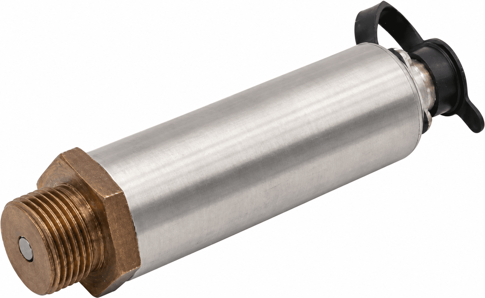
piezoresistive dynamic pressure sensor brushed steel cylinder bronze thread flush diaphragm black rear cap cyg401
Edited supplier photograph · CYG401

DC + DYNAMIC BRIDGE

PPS-PRZ-D10

DC + dynamic bridge pressure configuration

Not specified in source table; confirm gauge/absolute/reference

Source-documented configuration · quotation review required

Output
Differential millivolts; bridge-compatible conditioning
Pressure reference
Not specified in source table; confirm gauge/absolute/reference
Source temperature
-40 to +85 deg C or -55 to +125 deg C source options; confirm ordered option
Excitation
Source alternatives: 1 or 1.5 mA, or 12 VDC; select exact bridge variant
Mount
M20x1.5; source front nose span 12 mm. Usable engagement, seal and exact installation require confirmation.
Medium
non-corrosive, nonconductive media compatible with silicon and stainless steel
Conditioner choices
Source selection page lists 20/100/200 kHz options; this is not the bare-sensor flat bandwidth

Discrete source full-scale options; sensitivity is not paired by range in the inspected table.

Review PPS-PRZ-D10 dimensions & interfaces ↗
Source values & acceptance checks · PPS-PRZ-D10
CYG401 source pairs · checked 2026-11-16
Full scaleSource sensitivityNatural / resonant frequencyCatalogue rise timeVariant note
1 MPa / 10 bar / 145.0 psiNot range-paired180 kHz1 usSource pair; rise-time definition not given
2 MPa / 20 bar / 290.1 psiNot range-paired240 kHz1 usSource pair; rise-time definition not given
4 MPa / 40 bar / 580.2 psiNot range-paired320 kHz0.5 usSource pair; rise-time definition not given
6 MPa / 60 bar / 870.2 psiNot range-paired250 kHz0.5 usSource pair; rise-time definition not given
10 MPa / 100 bar / 1450.4 psiNot range-paired320 kHz0.5 usSource pair; rise-time definition not given
20 MPa / 200 bar / 2900.8 psiNot range-paired450 kHz0.3 usSource pair; rise-time definition not given
40 MPa / 400 bar / 5801.5 psiNot range-paired600 kHz0.3 usSource pair; rise-time definition not given
60 MPa / 600 bar / 8702.3 psiNot range-paired800 kHz0.2 usSource pair; rise-time definition not given
100 MPa / 1000 bar / 14503.8 psiNot range-paired1000 kHz0.2 usSource pair; rise-time definition not given

Natural frequency is not a flat bandwidth rating. No installed amplitude/phase calibration is established by this catalogue.

Confirm before a final specification

  • Confirm exact pressure reference, excitation, sensitivity and pinout for the quoted assembly.
  • Request usable installed response and the required calibration deliverables.
  • Obtain an approved dimensional/port drawing; catalogue dimensions do not establish a drop-in fit.
  • Constant-current bridge excitation is not a two-wire IEPE interface.
CYG401 supplier table and installation source ↗

This is catalogue evidence, not a serial-unit calibration certificate, stock confirmation or approved manufacturing drawing.

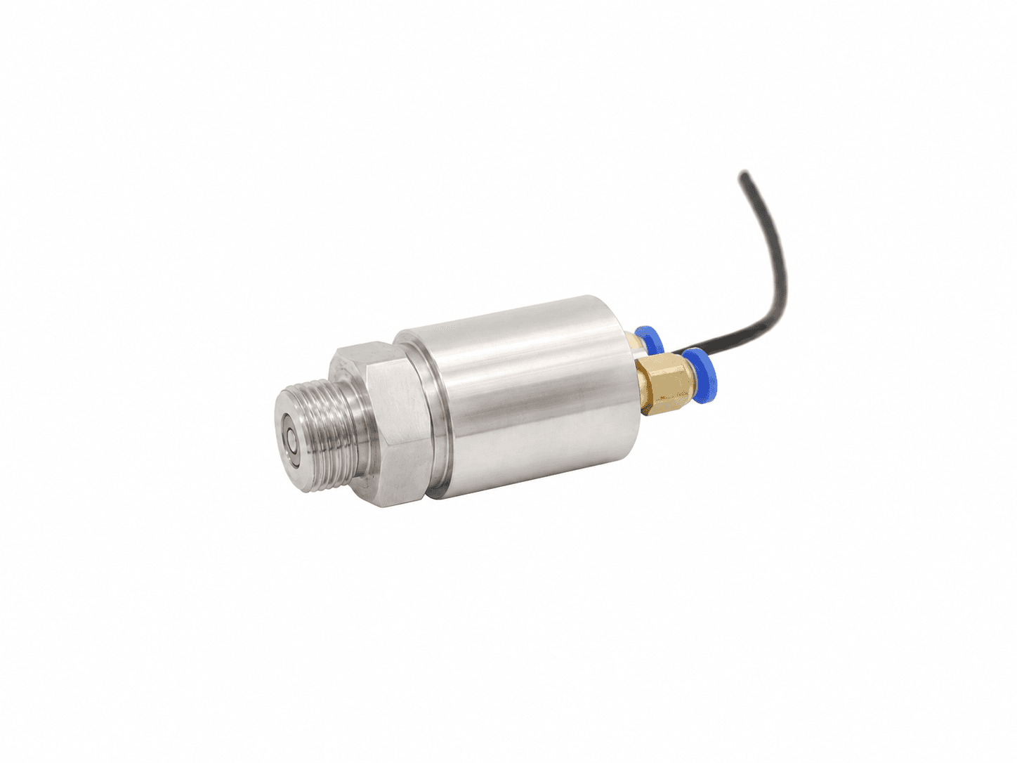
water cooled high frequency pressure sensor steel cylinder flush threaded diaphragm blue rear cooling ports cyg409
Edited supplier photograph · CYG409

DC + DYNAMIC BRIDGE

PPS-PRZ-C10

Water-cooled bridge pressure configuration

Not specified in source table; confirm gauge/absolute/reference

Source-documented configuration · quotation review required

Output
Differential millivolts; bridge-compatible conditioning
Pressure reference
Not specified in source table; confirm gauge/absolute/reference
Source temperature
0 to +450 deg C with specified cooling
Mount
M20x1.5 source drawing
Cooling
Source water pressure 300-700 kPa and flow 2 L/min; inlet temperature and full duty to confirm
Conditioning
Differential mV sensor; separately described nominal 0-5 V amplifier
Medium
non-corrosive, nonconductive, compatible with silicon/stainless steel
Excitation
Source alternatives: 1 or 1.5 mA, or 12 VDC; exact bridge variant to confirm

Source envelopes: 1-600 kPa or 1-100 MPa; exact discrete ranges are not enumerated. Submit a custom range for review.

Exact range requires engineering review; enter your pressure requirement in the RFQ.

Review PPS-PRZ-C10 dimensions & interfaces ↗
Source values & acceptance checks · PPS-PRZ-C10

Source natural-frequency envelope 200-1000 kHz is not paired to individual ranges. Rise time is described only as microsecond-level.

Confirm before a final specification

  • Confirm exact pressure reference, excitation, sensitivity and pinout for the quoted assembly.
  • Request usable installed response and the required calibration deliverables.
  • Obtain an approved dimensional/port drawing; catalogue dimensions do not establish a drop-in fit.
  • Gas/body/element temperatures differ. Source 450 deg C does not establish a 1093 deg C or uncooled rating.
CYG409 supplier table and installation source ↗

This is catalogue evidence, not a serial-unit calibration certificate, stock confirmation or approved manufacturing drawing.

miniature threaded dynamic pressure sensor flush diaphragm hex locknut slender stem cyg507
Edited supplier photograph · CYG507

DC + DYNAMIC BRIDGE

PPS-PRZ-M10

Miniature threaded bridge configuration

Gauge or sealed gauge; exact variant to confirm

Source-documented configuration · quotation review required

Output
Differential millivolts; bridge-compatible conditioning
Pressure reference
Gauge or sealed gauge; exact variant to confirm
Source temperature
-40 to +85 deg C or -55 to +125 deg C source options; confirm ordered option
Output level
Source 30-130 mV full scale; 80 mV typical, not range-paired
Mount
M2: M8x1 / Ø5.5 sensing tip; M3: M6x0.75 / Ø5 sensing tip; L1: Ø6.5 smooth rod. Confirm exact source outline.
Medium
compatible non-corrosive clean liquids and gases
Excitation
Source alternatives: 1 or 1.5 mA, or 12 VDC; exact four-wire option to confirm

Ranges retain their source diameter-group mapping. Ø5/Ø5.5 in the threaded sketches labels the pressure-end tip, not the complete body. Final interface/range pairing requires review.

Review PPS-PRZ-M10 dimensions & interfaces ↗
Source values & acceptance checks · PPS-PRZ-M10
CYG507 source pairs · checked 2026-11-16
Full scaleSource sensitivityNatural / resonant frequencyCatalogue rise timeVariant note
0.8 MPa / 8 bar / 116.0 psiNot range-pairedNot range-paired / not statedNot statedØ6.5 smooth-rod L1 source arrangement; no thread shown
1.6 MPa / 16 bar / 232.1 psiNot range-pairedNot range-paired / not statedNot statedØ6.5 smooth-rod L1 source arrangement; no thread shown
2 MPa / 20 bar / 290.1 psiNot range-pairedNot range-paired / not statedNot statedØ5 / M3 or Ø5.5 / M2 pressure-end tip groups; confirm exact variant
4 MPa / 40 bar / 580.2 psiNot range-pairedNot range-paired / not statedNot statedØ5 / M3 or Ø5.5 / M2 pressure-end tip groups; confirm exact variant
6 MPa / 60 bar / 870.2 psiNot range-pairedNot range-paired / not statedNot statedØ5.5 / M2 pressure-end tip group; confirm exact variant
8 MPa / 80 bar / 1160.3 psiNot range-pairedNot range-paired / not statedNot statedØ5.5 / M2 pressure-end tip group; confirm exact variant
10 MPa / 100 bar / 1450.4 psiNot range-pairedNot range-paired / not statedNot statedØ5.5 / M2 pressure-end tip group; confirm exact variant
20 MPa / 200 bar / 2900.8 psiNot range-pairedNot range-paired / not statedNot statedØ5.5 / M2 pressure-end tip group; confirm exact variant

Source natural-frequency envelope: 280-400 kHz for the 5/5.5 mm source diameter groups; 200 kHz for the 6.5 mm smooth rod. These are not calibrated flat bands or exact range-paired responses.

Confirm before a final specification

  • Confirm exact pressure reference, excitation, sensitivity and pinout for the quoted assembly.
  • Request usable installed response and the required calibration deliverables.
  • Obtain an approved dimensional/port drawing; catalogue dimensions do not establish a drop-in fit.
  • Conditioner selection lists 100/200 kHz choices but the standard-conditioner footnote says 20 kHz; confirm the exact high-bandwidth circuit.
CYG507 supplier table and installation source ↗

This is catalogue evidence, not a serial-unit calibration certificate, stock confirmation or approved manufacturing drawing.

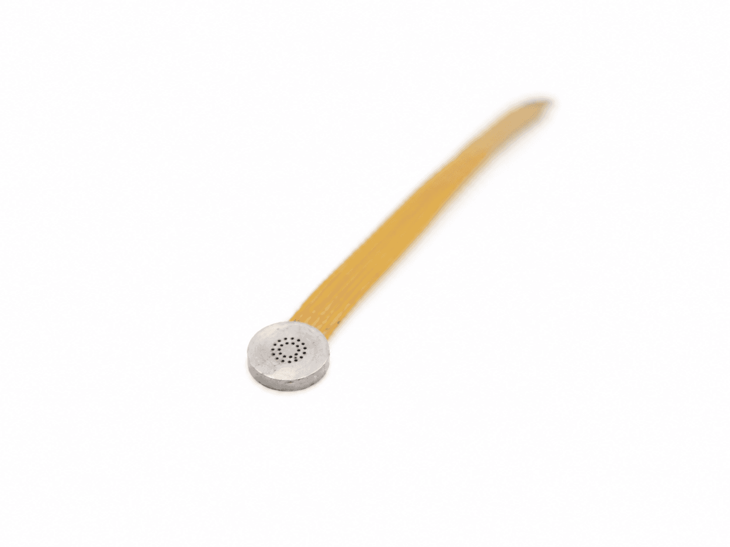
ultrathin mems pressure sensor dense perforated silver disc gold flex ribbon cyg512
Edited supplier photograph · CYG512

DC + DYNAMIC BRIDGE

PPS-PRZ-F10

Thin absolute surface-pressure configuration

Absolute

Source-documented configuration · quotation review required

Output
Differential millivolts; bridge-compatible conditioning
Pressure reference
Absolute
Source temperature
-40 to +85 deg C or -55 to +125 deg C source options; confirm ordered option
Package
1.2 mm source thickness; 6/8 mm diameter options, 0.15 mm flex
Excitation
Parameter table: 1 mA; ordering alternatives list 1.5 mA or 12 VDC. Resolve the exact bridge configuration.
Output level
Source 30-130 mV full scale; 80 mV typical, not range-paired
Medium
Source description: air; non-corrosive, nonconductive, dry clean gas only after confirmation
Conditioner limits
Source lists 20 kHz voltage-output conditioning; 4-20 mA footnote limits that output to 1 kHz. No 150 kHz chain is established.

Source absolute full-scale ranges include the static baseline. The required working headroom must be checked.

Review PPS-PRZ-F10 dimensions & interfaces ↗
Source values & acceptance checks · PPS-PRZ-F10
CYG512 source pairs · checked 2026-11-16
Full scaleSource sensitivityNatural / resonant frequencyCatalogue rise timeVariant note
0.05 MPa / 0.5 bar / 7.3 psi absoluteNot range-pairedNot range-paired / not statedNot statedAbsolute; diameter/range combination to confirm
0.1 MPa / 1 bar / 14.5 psi absoluteNot range-pairedNot range-paired / not statedNot statedAbsolute; diameter/range combination to confirm
0.15 MPa / 1.5 bar / 21.8 psi absoluteNot range-pairedNot range-paired / not statedNot statedAbsolute; diameter/range combination to confirm
0.3 MPa / 3 bar / 43.5 psi absoluteNot range-pairedNot range-paired / not statedNot statedAbsolute; diameter/range combination to confirm
0.6 MPa / 6 bar / 87.0 psi absoluteNot range-pairedNot range-paired / not statedNot statedAbsolute; diameter/range combination to confirm
1 MPa / 10 bar / 145.0 psi absoluteNot range-pairedNot range-paired / not statedNot statedAbsolute; diameter/range combination to confirm
1.5 MPa / 15 bar / 217.6 psi absoluteNot range-pairedNot range-paired / not statedNot statedAbsolute; diameter/range combination to confirm
3 MPa / 30 bar / 435.1 psi absoluteNot range-pairedNot range-paired / not statedNot statedAbsolute; diameter/range combination to confirm

No dynamic bandwidth, natural-frequency or rise-time number is stated in the inspected table. Do not infer 150 kHz capability.

Confirm before a final specification

  • Confirm exact pressure reference, excitation, sensitivity and pinout for the quoted assembly.
  • Request usable installed response and the required calibration deliverables.
  • Obtain an approved dimensional/port drawing; catalogue dimensions do not establish a drop-in fit.
  • This source drawing is 1.2 mm, not the 0.76 mm of certain original OEM flatpacks.
  • The 1 mA parameter table and 1.5 mA/12 VDC ordering alternatives require confirmation; they are not interchangeable supply settings.
CYG512 supplier table and installation source ↗

This is catalogue evidence, not a serial-unit calibration certificate, stock confirmation or approved manufacturing drawing.

Match the signal interface before the connector

Match the signal interface before the connector
RouteDC baselineConditioning decisionMain acceptance check
IEPE piezoelectricNot retained indefinitelyConstant current, bias, compliance and cable driveStatic preload, pulse droop and installed response
Charge-output piezoelectricFinite interval subject to droopCharge amplifier, input charge and time constantInsulation, cable hot zone and overload recovery
Tourmaline IEPE water probeNot retained indefinitelyIEPE electronics qualified for actual cable and immersionHydrostatic loading, acoustic geometry and sealing
Piezoresistive bridgeYes, with appropriate reference and chainBridge excitation, differential gain and headroomMean pressure, reference path, temperature and response

01 / ENGINEERING NOTES

How the catalogue screens a configuration

The filters narrow the eight documented arrangements by their recorded sensing route, DC capability, literal keyword and enumerated full-scale options. The numeric filter keeps a model only when at least one documented full scale is at or above your entry. Its range selector then shows those eligible options. An unpaired range envelope is not converted into invented orderable steps.

  • No entered minimum: all documented ranges remain available.
  • A numeric minimum excludes the cooled C10 record because its exact range steps are not enumerated.
  • Matching a pressure ceiling is a screening result. It is not an automatic recommendation or qualification.

02 / ENGINEERING NOTES

Choose the pressure reference and headroom next

Absolute, gauge, sealed gauge and dynamic excursion are different requirements. An absolute full scale includes the steady baseline; a small fluctuation on a large mean pressure can exceed amplifier headroom before the desired signal is resolved. Specify baseline, positive and negative extrema and allowable overload separately. The DC checkbox identifies a sensing principle, not the complete accuracy or reference arrangement.

03 / ENGINEERING NOTES

Keep sensitivity attached to its source range

The IEPE F10 source pairs 1 MPa with 5,000 mV/MPa and 100 MPa with 50 mV/MPa. The charge F10 source pairs 1 MPa with 5,000 pC/MPa and 60 MPa with 120 pC/MPa. These are different electrical quantities. Multiplying the stated nominal range and sensitivity is a headroom cross-check, not a calibrated output guarantee; bias, overload and usable voltage or charge span still need review.

04 / ENGINEERING NOTES

Do not filter by resonance as if it were bandwidth

The D10 source supplies range-dependent natural-frequency and rise-time pairs. C10 gives only a natural-frequency envelope; M10 groups frequency by body diameter; F10 thin bridge has no published sensor bandwidth in the inspected table. Those evidence levels do not support a comparable calibrated bandwidth filter. Request the usable amplitude and phase response of the sensor, mounting, cable, conditioner and recorder.

05 / ENGINEERING NOTES

Read source dimensions as interface clues

A thread diameter does not establish pitch, seal location, diaphragm depth or engagement. On the flush piezoelectric sources, M10×1 is the pressure mount while M5 labels the electrical output without a stated pitch or pinout. The cooled bridge source uses M20×1.5. The miniature bridge drawings show alternatives that must be matched to the body and range; the thin package source is 1.2 mm thick. None of these summaries replaces an approved installation drawing.

06 / ENGINEERING NOTES

Temperature and conditioning are separate choices

The sourced charge F10 is limited to +150°C and the sourced IEPE F10 to +120°C. They do not establish an extreme-temperature combustion assembly. The cooled C10 source describes 0–450°C with specified water cooling; gas, body and sensing-element temperatures remain separate. Confirm the cable, connector, excitation, gain and usable conditioner response for the exact assembly. Specialist cooling and hot-zone components need a separate quotation.

07 / ENGINEERING NOTES

Example: retain a DC baseline with at least 1 MPa full scale

Illustrative catalogue inputs: select DC baseline required and enter 1 MPa, leaving the sensing-route filter at All. D10, M10 and thin F10 have eligible enumerated ranges. C10 is excluded because its range envelope is unpaired. These software matches still need pressure-reference, medium, mounting and installed-response checks; the thin absolute F10 is not automatically suitable for a liquid line.

08 / ENGINEERING NOTES

Example: choose an IEPE full-scale option above 5 MPa

Illustrative inputs: choose IEPE piezoelectric and enter 5 MPa. The flush F10 and air-probe P10 remain visible. Their sensing geometries differ: a threaded flush port and a free-field air probe cannot be exchanged because both pass a range filter. Select the actual geometry, then choose a listed range and review its paired sensitivity.

09 / ENGINEERING NOTES

Example: an incompatible DC and tourmaline request

Choose the tourmaline IEPE route and require a retained DC baseline: the catalogue returns no match. Clear the DC filter for a dynamic water-probe review, or investigate a suitably qualified DC-capable pressure route. A no-match result describes these eight records only; the custom RFQ is available for requirements outside this set.

010 / ENGINEERING NOTES

Download a technical brief, then confirm the offered unit

Each PDF is generated from the same configuration data as this page and identifies the source model, range pairs, revision and unresolved checks. It is a shareable selection brief. The final quotation should identify the exact assembly, approved drawing, output and excitation, material/media limits, response evidence and calibration deliverables. No serial-unit certificate, stock quantity or manufacturing acceptance is established by a catalogue PDF.

Pressure-chain questions for this configuration

Are these released stock SKUs?

The PPS codes identify source-documented quotation configurations. Availability, exact options, accepted specification, price and delivery are confirmed for the offered assembly in writing.

What does a pressure-filter match mean?

At least one enumerated source full scale meets or exceeds the entered value. The match does not establish pressure-reference compatibility, headroom, media suitability or installed dynamic response.

Why does the cooled model disappear with a numeric minimum?

Its source gives broad range envelopes without discrete paired order options. The catalogue does not invent those steps; clear the minimum and submit the required range for engineering review.

Does the DC checkbox qualify a complete static-pressure channel?

No. It identifies a bridge sensing route. The pressure reference, excitation, gain, temperature behavior and full-scale headroom still need review.

Why is there no bandwidth filter?

The sources publish different quantities: resonance, diameter-group frequency envelopes or no sensor frequency figure. Comparable calibrated usable bandwidth is not established for all records.

Does a 1 mA bridge supply mean IEPE?

No. Constant-current bridge excitation and a two-wire IEPE interface are different electrical arrangements. Match the actual pinout, excitation and conditioning.

Is an M5 output connector an M5 pressure port?

No. The source distinguishes the electrical output from the M10×1 pressure mount. The connector pitch and pinout must be confirmed independently.

Are the underwater photographs PVDF needle hydrophones?

The U10 reference is an edited supplier rendering of a tourmaline IEPE water probe. It does not depict a PVDF needle hydrophone or establish a 50 ns response.

Can the sourced charge F10 be ordered as a 650°C sensor?

Its source limit is +150°C. A 650°C requirement needs a separately qualified package, cable, connector and conditioning chain; this record does not establish it.

Can I edit the range after selecting a configuration?

Yes. The selected code and range populate the RFQ, and you can edit the pressure requirement before submitting. Accessory selection preserves that current requirement.

Do PDF briefs contain calibration certificates or CAD?

No. They contain source-based configuration data and acceptance questions. Request the actual serial-unit calibration record and approved drawing or CAD for the proposed assembly.

Can I use this catalogue without JavaScript?

All model cards, source tables, native disclosures, PDF downloads and RFQ links remain readable. Interactive filters and inline form submission require JavaScript; the designated email remains available.

Sources and scope of the comparison

Original-model facts and general methods describe their named sources. They do not qualify a PPS unit or imply manufacturer affiliation.
COMPLETE THE PRESSURE MEASUREMENT CHAIN

Specify conditioning, mounting and protection together.

Optional budget requests. Confirm the input type, response, channel count and installed compatibility. Specialist hydrophone preamplifiers, hot-zone hardline cables and cooled assemblies are quoted separately.

Review selected configuration ↘

PREPARE A REVIEWABLE BRIEF

Download the worksheets for your project.

These are blank engineering request/checklist documents. They are not released product datasheets, calibration certificates or signed quotations.

ENGINEERING RFQ / PPS CONFIGURATIONS / RANGE TO RFQ

Send this pressure configuration for review.

Include the original suffix and a private installation drawing when available. Final specifications, evidence, price and lead time are confirmed in writing.

PPS configuration catalogue

Pressure event & project contact
Document package requested

Optional requests for the exact offered assembly. Availability, scope and approval are confirmed during quotation.

Accessory requests for this chain

Opt in to the items you need. These are budget requests; compatibility, channel count and final price require review.

Bring the whole pressure event into focus.

Discuss your application ↗