REQUEST A CONFIGURATION / PPS SERIES
Select the signal and installation you need.
PPS codes below identify inquiry families. The table defines what to review; it does not assign an unverified pressure, temperature or bandwidth rating to a supplied unit.
| Configuration request | Pressure / task | Electrical chain | Installation review | Next step |
|---|---|---|---|---|
| PPS-CHG-HTCharge output for thermal exposure | Pressure range and duration supplied in the RFQ | pC/bar or pC/psi; external charge amplifier | Crystal, insulation, cable hot zone and time constantOriginal charge model + temperature duty | Request this family ↘ |
Thermal-duty specification worksheet
| Decision | Supply in the RFQ | Acceptance evidence |
|---|---|---|
| Hot zone | Gas temperature, body temperature, exposure duration and cycling | Exact packaged sensor, seal and cable temperature limits |
| Pressure event | Mean pressure, dynamic peak, pulse duration and lowest frequency | Range, sensitivity, discharge time constant and drift |
| Charge chain | Sensitivity, cable route, insulation and amplifier location | Input charge headroom, gain, passband and recorder swing |
| Protection | Cooling or flash-thermal protection requirement | Response and thermal-error evidence for the complete assembly |
01 / ENGINEERING NOTES
An original high-temperature example shows the trade-off
Piezocryst’s CP-Series datasheet gives CP5x6 continuous operation to 650°C and short-term exposure to 700°C, while its stated working frequency range is 1 Hz–10 kHz. The same table gives separate connector limits. PCB Piezotronics’ 176A33 is another original charge-output design, specified for continuous operation to 760°C. These are named OEM examples, not PPS ratings or evidence that every high-temperature sensor has a microsecond measurement band.
02 / ENGINEERING NOTES
A crystal limit is not a packaged-sensor rating
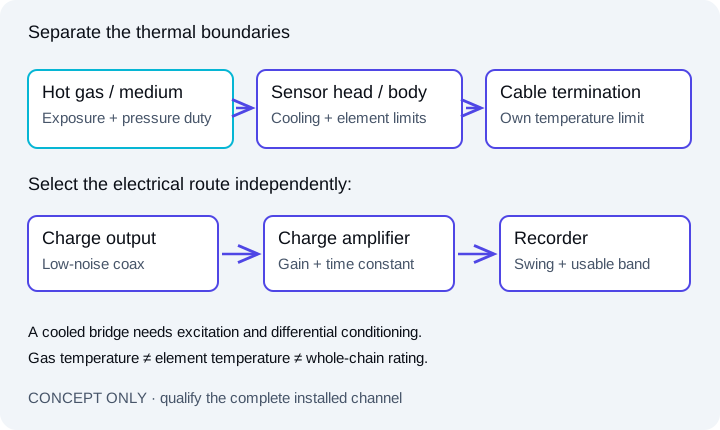
The sensing crystal is only one part of a pressure transducer. Electrical insulation, diaphragms, seals, joining processes, connectors and cable terminations also constrain temperature. A wide temperature objective such as −240°C to +650°C needs a specifically qualified assembly; it cannot be inferred from the words quartz or charge mode.
- State continuous, intermittent and flash exposure separately.
- Include heat-up/cool-down rates, pulse count and required operating duration.
- For cooled installations, provide coolant conditions and body-temperature monitoring requirements.
03 / ENGINEERING NOTES
Retain the pressure feature that matters
Charge-mode sensing does not retain a truly static signal indefinitely. A long time constant can preserve a finite plateau but may increase recovery time after overload or thermal transients. For thermoacoustic work, define the lowest frequency, smallest pulsation and required phase tolerance as well as the fastest edge.
- Specify mean pressure and permitted dynamic excursion separately.
- Ask for the thermal-transient error and zero-recovery behavior appropriate to the test.
- Use a separate DC-capable channel when the steady baseline is a required measurand.
04 / ENGINEERING NOTES
Keep the amplifier outside the unqualified hot zone
A raw charge output requires a compatible charge amplifier or converter. Low insulation resistance and cable motion can corrupt a small signal; maximum input charge and output voltage can limit a large one. Route and support the cable using the limits of the exact cable assembly, including its connector and termination.
- Review sensitivity × peak pressure against amplifier input charge and selected gain.
- Confirm cable type, length, connector, shielding, grounding and hot-zone transition.
- The T499 source reference has a 0.5 Hz–100 kHz passband; it is not evidence of a 200 kHz or 650°C chain.
05 / ENGINEERING NOTES
Use the source references for the right question
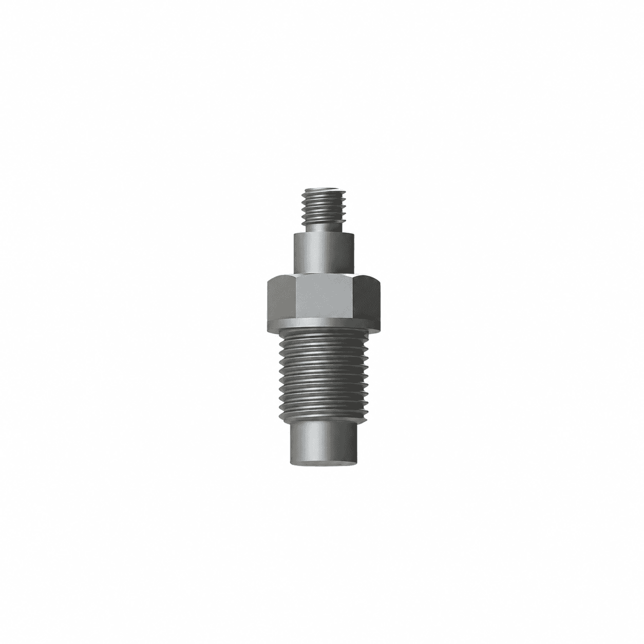
The KD2004 source rendering illustrates a charge-output pressure package. Its published −40°C to +150°C limit does not substantiate an extreme-temperature PPS configuration. Submit the full original model and thermal-duty drawing so the offered unit can be reviewed against the requested operating conditions.
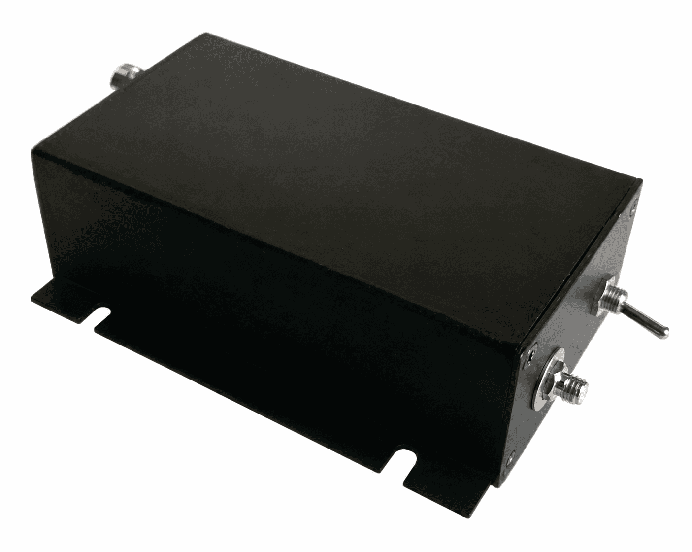
These are source references. The T499 is a charge amplifier with a source response of 0.5 Hz–100 kHz (−3 dB±1 dB), 1–10 mV/pC gain and ±10 V output; it is not a 200 kHz IEPE instrument. Sensor temperature and conditioning limits require separate review.
SOURCE-DOCUMENTED HARDWARE REFERENCES
Review the package and its sensing principle.
These supplier-reference images show the indicated arrangements. Final pressure, medium, dimensional and response requirements are confirmed for the proposed configuration.
AT THE PRESSURE PORT
The installed passage changes the recorded event.
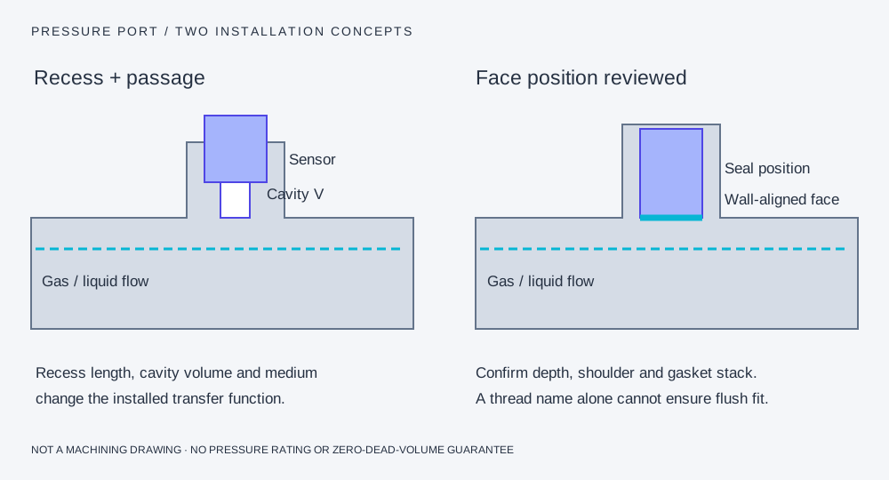
A recess adds an acoustic system.
A small cavity and connecting passage can add amplitude peaking, ringing and delay. A tapered pipe thread does not set a reproducible diaphragm depth.
Flush alignment needs dimensions.
Match the front face, sealing shoulder, gasket compression and allowed protrusion/recess. A protection layer or screen also belongs in the installed response review.
Pressure-chain questions for this configuration
Does charge output automatically mean 650°C operation?
No. The complete pressure package, insulation, seals, cable and installation need a stated temperature rating for the required exposure. Charge output alone does not establish it.
Can a high-temperature charge sensor replace a static pressure channel?
Only for a defined finite measurement interval with acceptable droop. A continuously retained static baseline requires an appropriately qualified DC-capable pressure channel.
Sources and scope of the comparison
- PCB Piezotronics: pressure-sensing principles and installation
- KD2004 supplier charge-pressure source: arrangement and stated limits
- Piezocryst CP-Series: separate head, cable, connector and frequency limits
- PCB Piezotronics 176A33: original high-temperature design
Original-model facts and general methods describe their named sources. They do not qualify a PPS unit or imply manufacturer affiliation.